Week 2 Bevel Gear Challenge
Aim : To understand the concept of the grid dependency test and then run the simulation on bevel gear with 4mm, 5mm and 6mm element size to evaluate the von-mises stress, equivalent stress and total deformation on the bevel gear.
Grid Dependency Test - This is the procedure of getting the analysis done in step wise format like from coarse mesh to refined mesh by slowly getting finer mesh for each run until the result doesn't changes abruptly.
- The concept of this test is find optimum mesh size for the evaluation, where it is neither too coarse mesh nor too finer mesh.
- As the mesh gets finer the no. of nodes and elements increases thereby making the solver to take more time and resources.
Procedure:
- Select Static Structural in Ansys Workbench. Select the material to be Structural Steel. Import the model using import tool from the location.
- Do editing on the model using SpaceClaim and remove the central area of the gear concentric to hole. In order to reduce the no. of nodes and elements for computaion thereby reducing the computational time.
- Open the geometry edit option and enter various parameters after renaming both gears as small gear and big gear for proper identification. Then select the material to structural steel in drop down menu for each component.
Contacts :
- For contacts module set rename the contact to Renamed Based on definition. Then select the frictional small gear to big gear.
- Select the faces for contact body - All the faces which will come in contact while analysis.
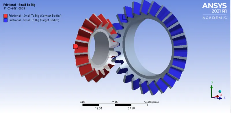
- Select the contact type to be frictional with following parameters to be entered.
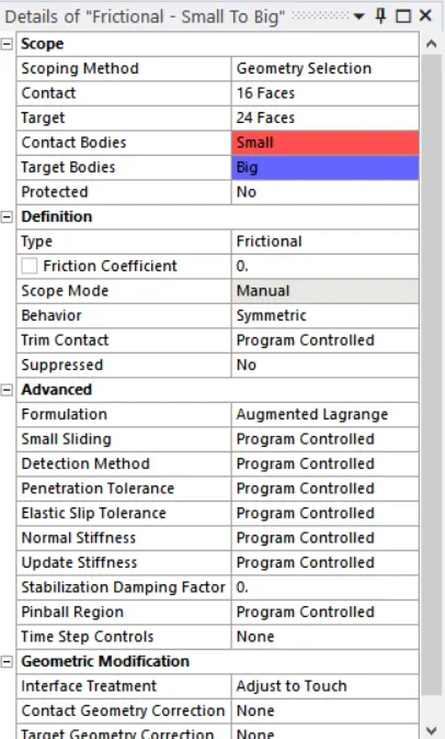
Joints:
- Make a folder of joints in connections. Two revolute joints will be provided for big gear and small gear as Body-Ground connection.
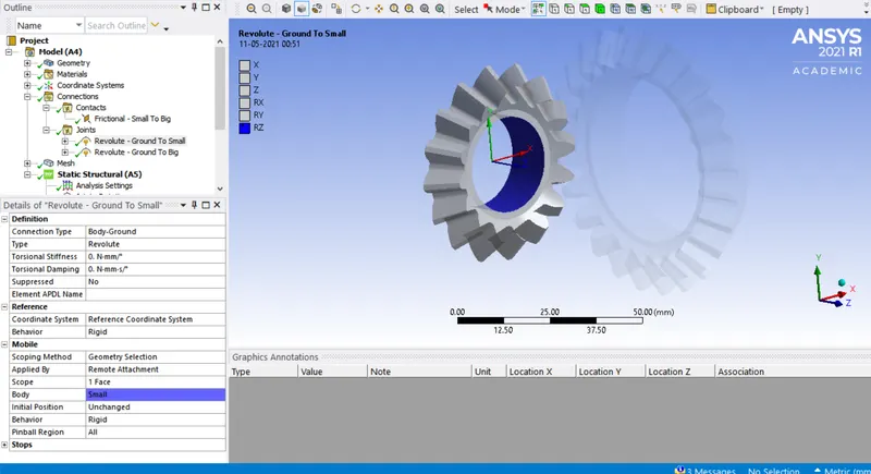
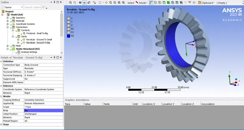
Mesh:
- Make the mesh parameters by selecting the bodies for meshing with default mesh size.
- Now introduce the mesh element size to 6mm to portion on contact by using sizing option from the mesh toolbar after selecting those portions.
- Here as we are doing grid dependency test we have to change the selected area mesh size in decreasing order for each simulation in the sequence of 6mm ,5mm and 4mm.
Analysis Settings:
- Here we are taking simulation in 6 steps with following settings.
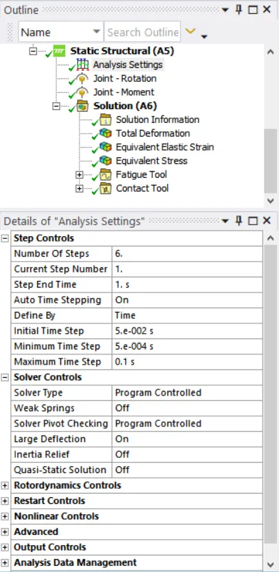
- Now insert the joint loads. For Small gear select Revolute Ground to small, in type select rotational and in magnitude be it tabular as shown below:

- Similarly for big gear select the Revolute Ground to Big, in type select Moment and in magnitude be it tabular with value of 100 Nm for each step.
- Make sure the rotation direction for both the gears are in opposite directions.
- To obtain result select the parameters as Total deformation, Von Mises Stress & Equivalent Elastic Strain.
Result:
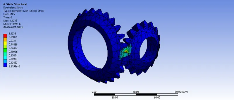
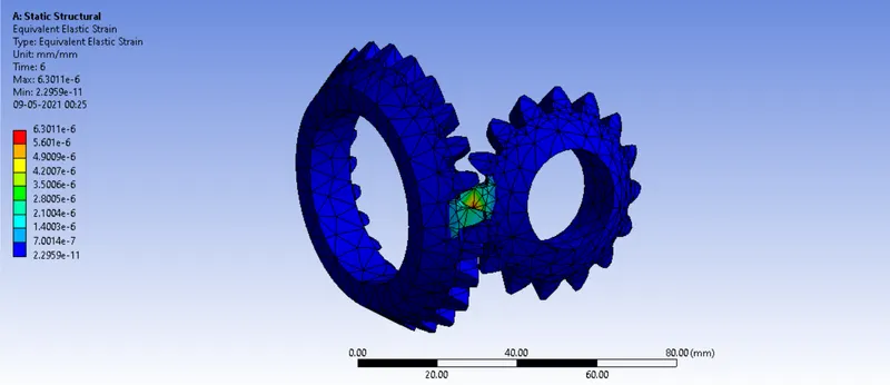
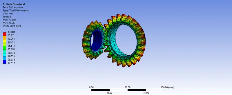
Case 1 : For 6mm size:
Equivalent Stress:
Equivalent Strain:
Total Deformation :
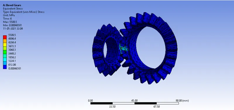
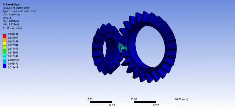
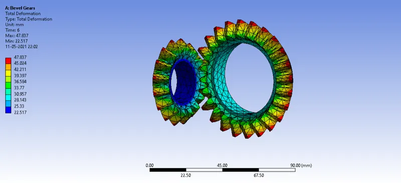
Case 2 : For 5mm size:
Equivalent Stress:
Equivalent Strain:
Total Deformation:
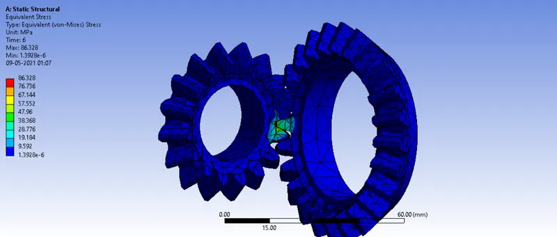
Case 3: For 4mm Size :
Equivalent Stress:
Equivalent Strain:
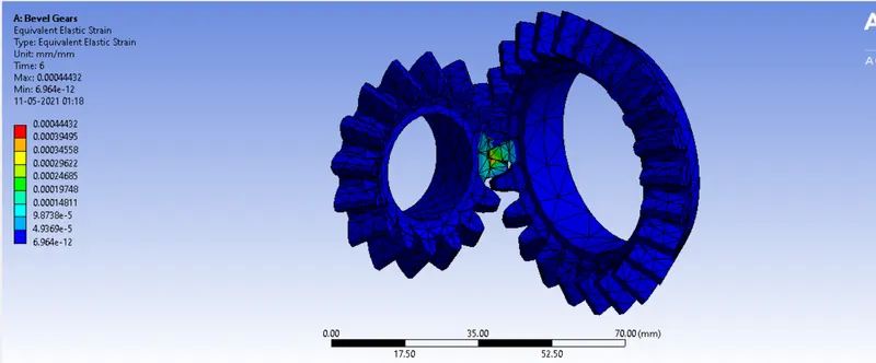
Total Deformation:
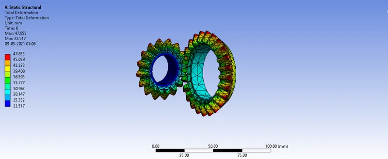
Final Result:
| Mesh Size | Equivalent Stress | Equivalent Strain | Total Deformation | |||
| Min (Mpa) | Max (Mpa) | Min | Max | Min (mm) | Max (mm) | |
| 6 mm | 3.2 e-6 | 1.2 | 2.29e-11 | 6.3e-6 | 22.5 | 47.8 |
| 5 mm | 4.6e-4 |
5.5e3 |
2.3e-9 | 3.1e-4 | 22.5 | 47.8 |
| 4 mm | 2.04e-6 | 60.9 | 2.3e-11 | 3.3e-4 | 22.5 | 47.8 |