Week 2 Bevel Gear Challenge
OBJECTIVE:
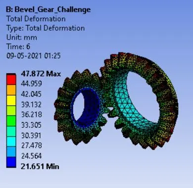
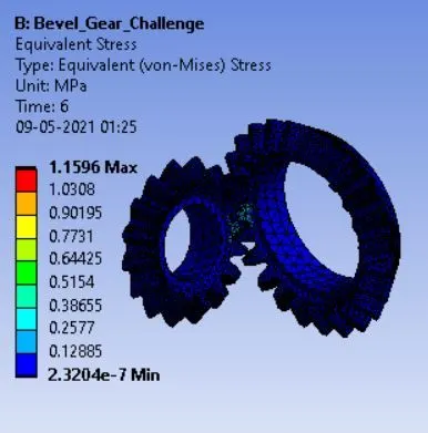
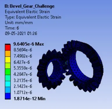
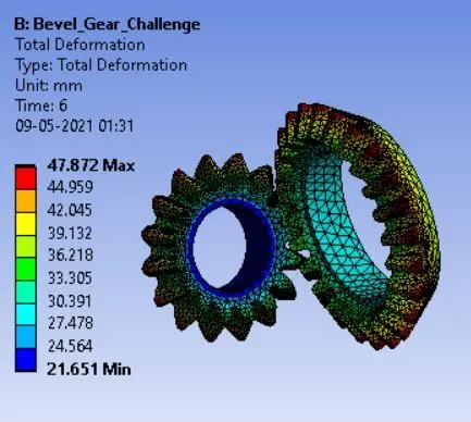
1. To run a Grid Dependency study for the provided model of Bevel Gears for mesh sizes 6mm, 5mm, 4 mm and evaluate and compare the simulation results for von-mises stress, equivalent elastic strain, and total deformation.
2. Explain the grid dependency test.
CASES:
what is the Grid Dependency Test?
The grid dependency test is to investigate how the solution depends on the grid size by running the simulation with refined mesh that is finer the mesh, higher is the accuracy of the result but with additional cost on computation time and computational power. Since solutions are interpolated at the nodes to get an approximate result, the higher the number of nodes and elements higher is the computational time and power required to complete the simulation.
So, the grid dependency test helps in determining optimal mesh size where the accurate result could be obtained keeping in the mind the cost of time and power. Since the result obtained are approximate, refining mesh further would result in a negligible per cent change in the result but only increase the computational cost.
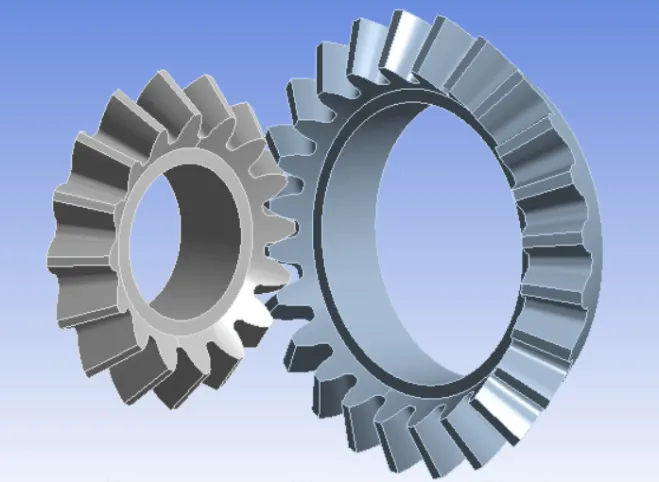
CAD MODEL (BEVEL GEAR):
MATERIAL USED:
PROCEDURE:
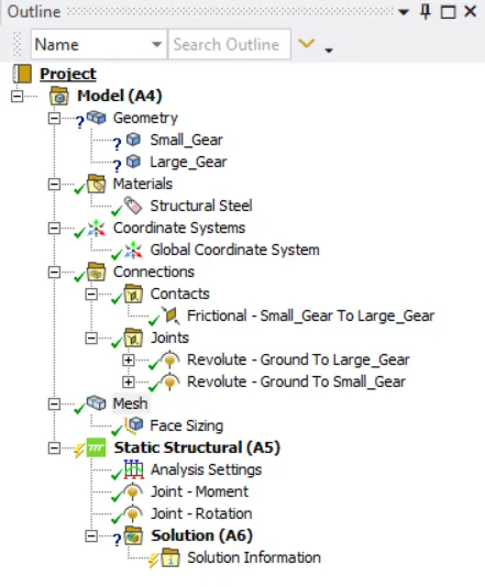
After renaming the model, applying material we now apply mesh and joint loads.
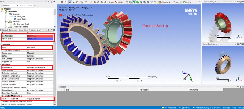
CONTACT SETUP:
We setup contact for both gears by providing following parameters and selecting the teeth faces of the gears.
APPLICATION OF JOINT LOADS:
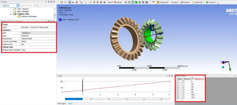
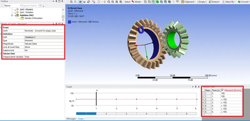
Apply rotation to small gear and moment to the big gear and enter the parameters as shown in the images below:
Small Gear:
Big Gear:
GENERATE MESH:
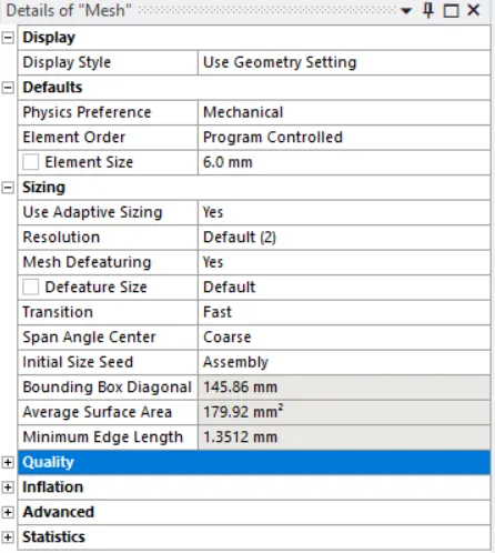
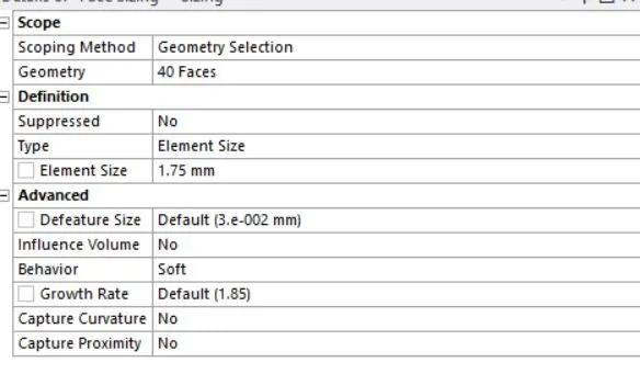
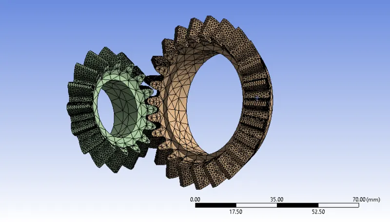
Now after applying loads and joints we proceed to mesh generation:
Global Mesh size = 6 mm
Face sizing = 1.75 mm
Connections Details:
Contacts: Contact Body = Small Gear (Faces = 16)
Target Body = Big Gear (Faces = 24)
Type: Frictional
Behavior = Symmetric
Formulation = Augmented Lagrange
Interface Treatment: Adjust to Touch
Joints: Joint_1
Connection Type: Body-Ground
Type: Revolute
Body: Big Gear
Joint_2
Connection Type: Body-Ground
Type: Revolute
Body: Small Gear
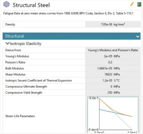
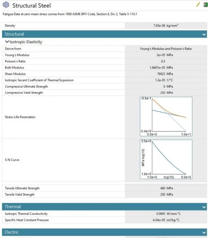
Material Specifications:
Boundary Conditions:
Here we are going to look at contact forces, traces and stress developed for the revolution of gear. So for 120-degree angle, In analysis settings give values as given below:
No. of Steps = 6
Auto Time stepping = ON
Defined by = Time
Initial Time Step = 0.1 s
Minimum Time Step = 0.05 s
Maximum Time Step = 0.2 s
Select “Large Deflection on”
Other Boundary conditions for joints are as given below:
Joint Load :
Joint: Revolute – Ground to Big_Gear
Type: Moment
Magnitude: Tabular Data
Boundary Conditions:
Here we are going to look at contact forces, traces and stress developed for the revolution of gear. So for 120-degree angle, In analysis settings give values as given below:
No. of Steps = 6
Auto Time stepping = ON
Defined by = Time
Initial Time Step = 0.1 s
Minimum Time Step = 0.05 s
Maximum Time Step = 0.2 s
Select “Large Deflection on”
Other Boundary conditions for joints are as given below:
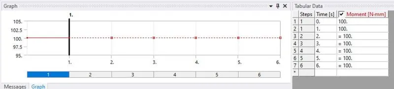
(1) Joint Load :
Joint: Revolute – Ground to Big_Gear
Type: Moment
Magnitude: Tabular Data
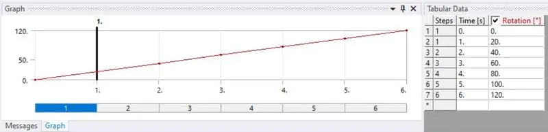
(2) Joint Load :
Joint: Revolute – Ground to Small_Gear
Type: Rotation
Magnitude: Tabular Data
Solution:
- After giving proper boundary conditions, create desired solutions for output results.
- Create Solutions for “Equivalent (Von Mises) Stress”, “Equivalent (Von Mises) Strain” and “Total Deformation”.
Parameterization:
- Now before solving for requested results, we have to give parameters to the Input as well as Output side.
- For Input parameters, we will give Mesh size and for Output parameters, we can give Minimum and maximum values for stress, strain and deformation results.
- So we can select checkboxes given for input and output parameters as their locations as given below:
- After the creation of Parameters, solve the results and close the mechanical module, we can see Parameter Set has been activated as given below:
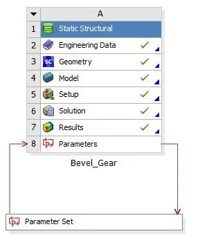
- Create new design points for 5 mm and 4 mm mesh and make sure that the “Retain” option is enabled.
- After giving all design points select “Update All Design Points” and get results for all design points.
- Results for updated design points will be as given below
Results:
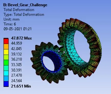
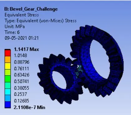
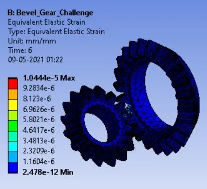
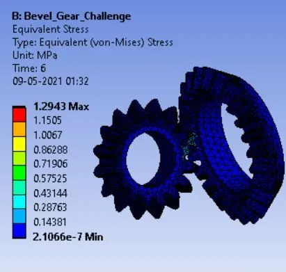
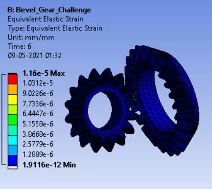
By setting each Design Point as current, we can get results for each case as below:
CASE_1: 6 mm
CASE_2: 5 mm
CASE_3: 4 mm
Conclusions:
