Week 2 Bevel Gear Challenge
Grid dependency test
Grid dependency test or mesh refinement test are perform in finite element analysis to get the best suitable mesh size and optimum simulation time. To perform grid dependency test usually we mesh given geometry and perform simulation and get the result after that we again mesh finer size mesh and get result, we form this procedure till we get result with minimum error or negligible difference.
Example. While performing maximum stress test for any component let we analysis simulation with course mesh and we get any result, after that we reduce mesh size by some amount and repeat the test. This test is repeated until we get negligible difference in result. The conclusion of this test we consider the mesh size which is max for these negligible result. So that we make a decision to get best result without any error or minimum error in best time ( as we know large simulation time while performing too fine mesh or low accuracy and less time while we perform with course mesh).
Hence engineer must aware about the best meshing size for any component, to know this meshing size engineer must have to perform grid dependency test.
Objective: perform grid dependency test on Bevel gear system for mesh size 6, 5 and 4 mm.
Procedure:
Here we will perform the Static Structural analysis test , the simulation will be run on three different mesh size which is 6 , 5 and 4 mm. before this we will perform simulation on default mesh size and we will map teeth face size by 1.75 mm. later we will refine mesh size using parametric tool.
We imported the geometry and remove the unrequired part/section before simulation to reduce the simulation run time. We edit the geometry in spaceclaim tool under ANSYS workbench software.
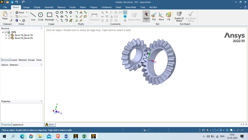
The material assign to the geometry is Structural steel and the property of the material is shown below
Density: 7.85e-06 kg/mm³
Isotropic Secant Coefficient of Thermal Expansion : 1.2e-05 1/°C
Young's Modulus : 2e+05 MPa
Poisson's Ratio : 0.3
Bulk Modulus : 1.6667e+05 MPa
Shear Modulus : 76923 MPa
Tensile Yield Strength : 250 MPa
Compressive Yield Strength : 250 MPa
Tensile Ultimate Strength: 460 MPa
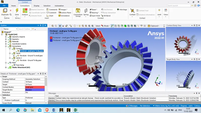
After geometry clean up and material setup we will move to model and 1st we will rename the geometry to small gear and big gear based on their size to simplicity. And contact between both the gear are define as below setting

Contact body: small gear, target body: Big gear
Contact and target are teeth of respective gears.
Type: frictional
Behaviour: Symmetric
Formulation: augmented Lagrange
Stabilization damping Factor: 1
Interface treatments: Adjust to touch
(Rest setting as it is)
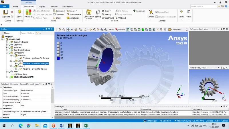
After this we had given two revolute joint given, one for each gear
Connection Type : body to ground
For the analysis setting , below setting are applied
No of step : 6
Auto time stepping: on
Define by: time
Carry over time step: off
Initial time step: 0.2 s
Minimum time step: 0.1 s
Maximum time step: 1 s
Weak spring: program controlled
Large deflection: on
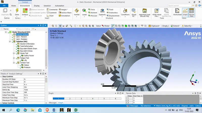
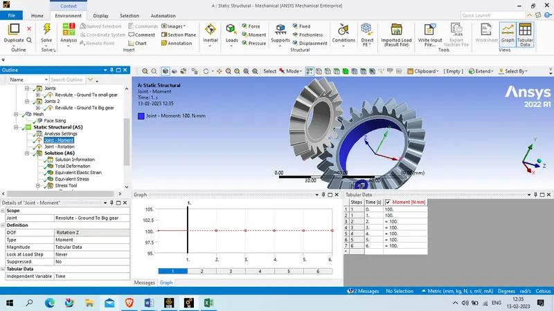
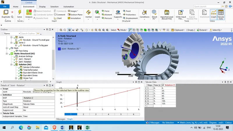
We define to two joint load, for big gear we provide moment of 100 N load at each step in anticlockwise direction using tubular data and for small gear we define rotation of 20 degree at each step in clockwise direction using tubular data.
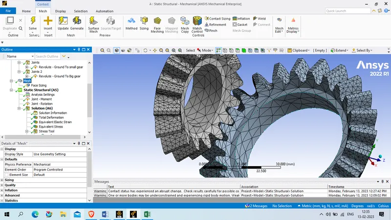
For mesh local mesh size on face is provided on both gear teeth face with size of 2 mm. and rest mesh was provide as default size , later we will define this with 6, 5 and 4 mm to perform grid dependency test.
Pictures :
Mesh size : default, Face mesh size : 2
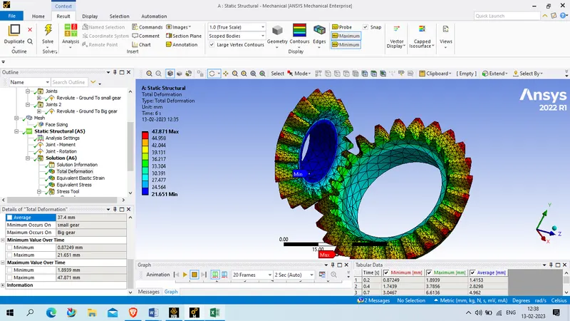
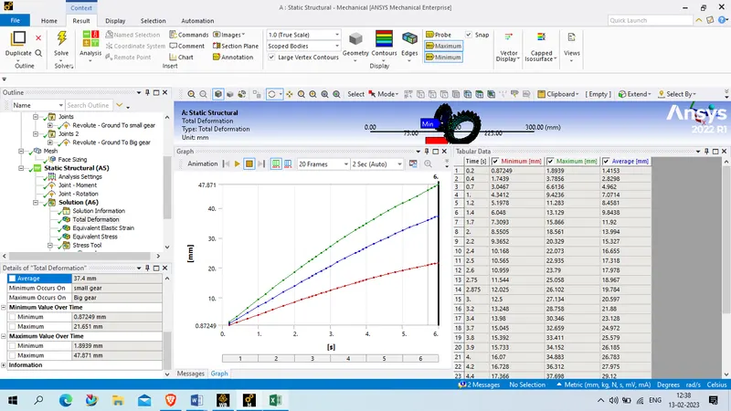
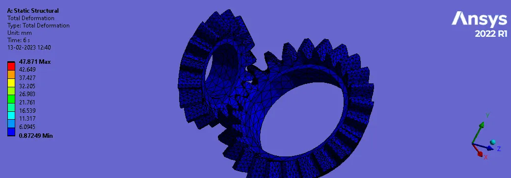
Deformation
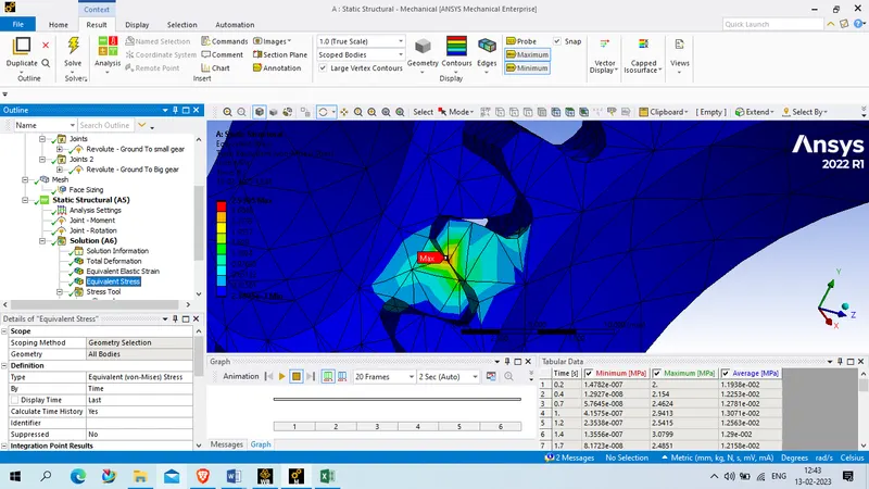
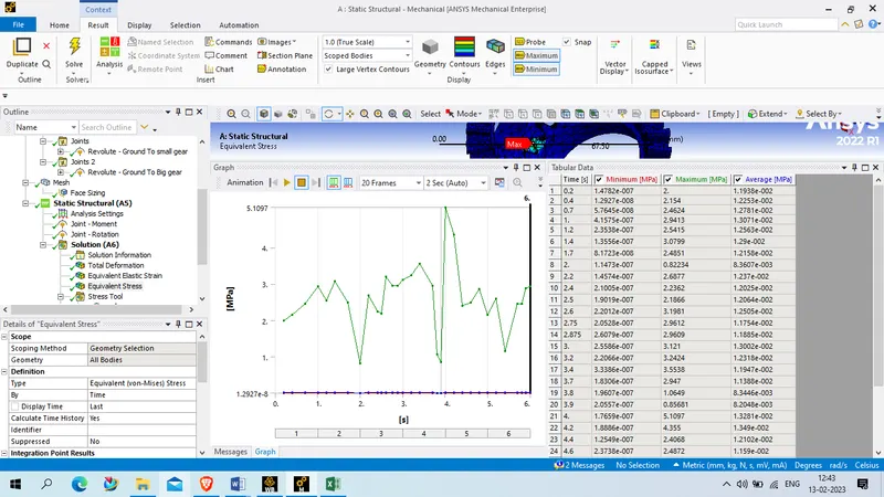
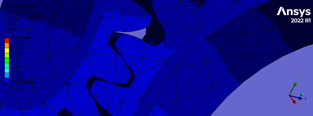
equivalent Stress (Van-mises)
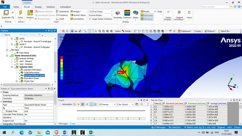
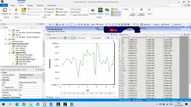
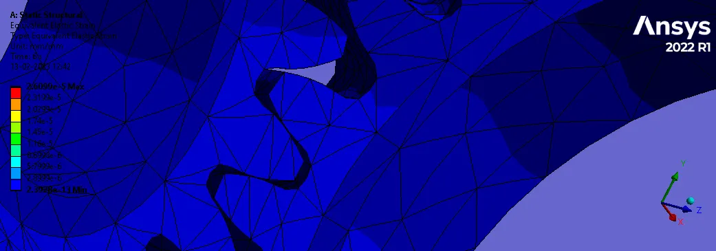
Equivalent strain :(van-Mises)
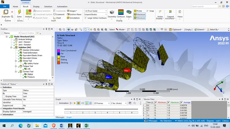
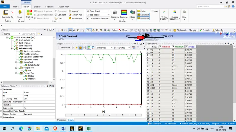
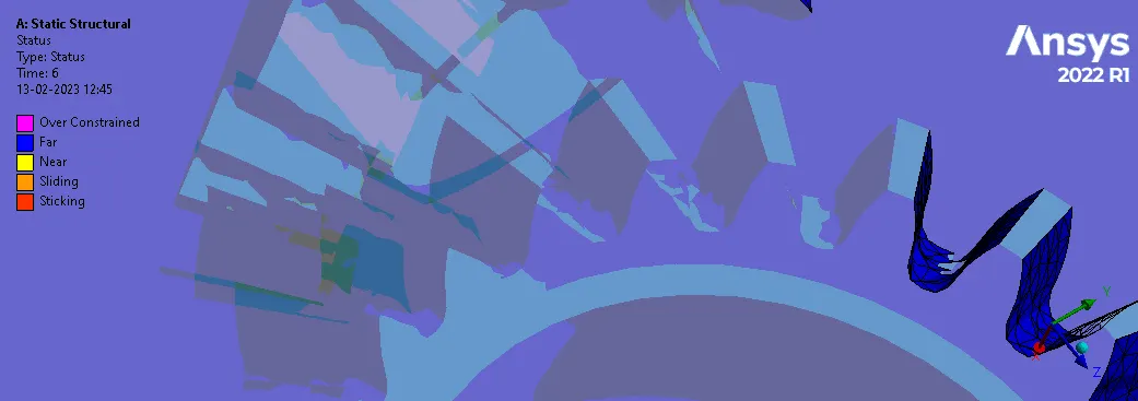
Contact status :
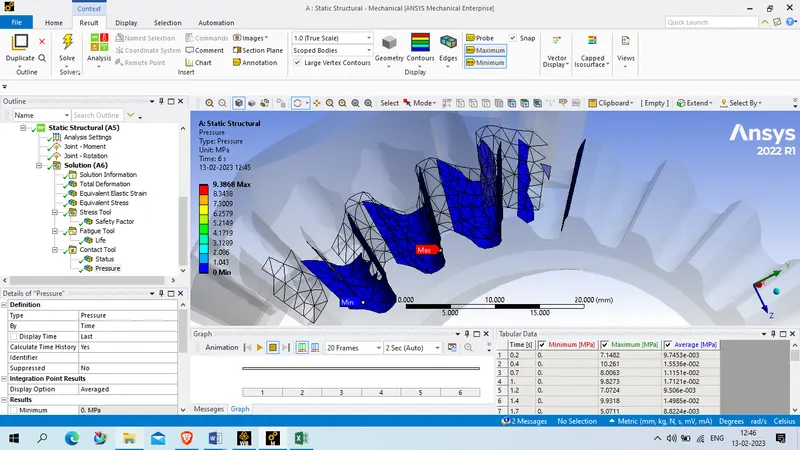
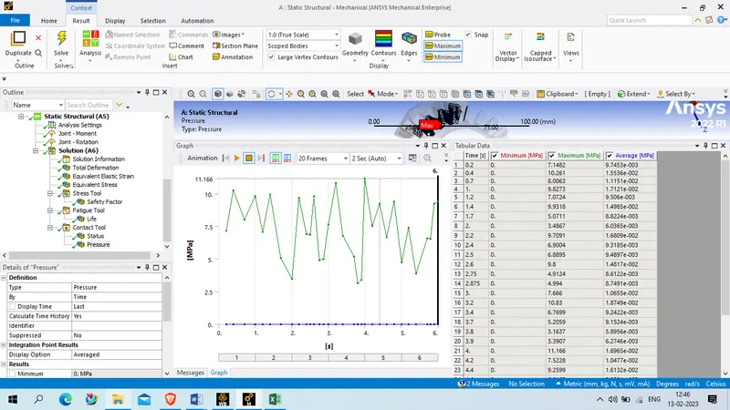
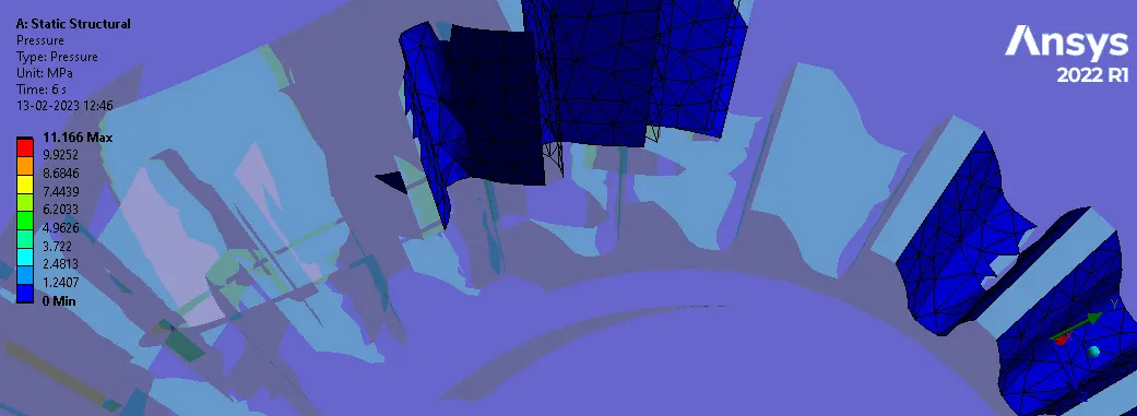
Pressure :
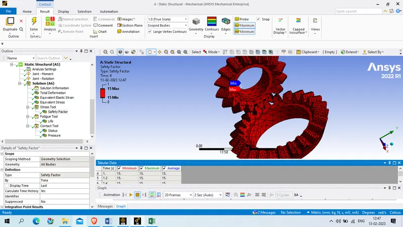
safety Factor
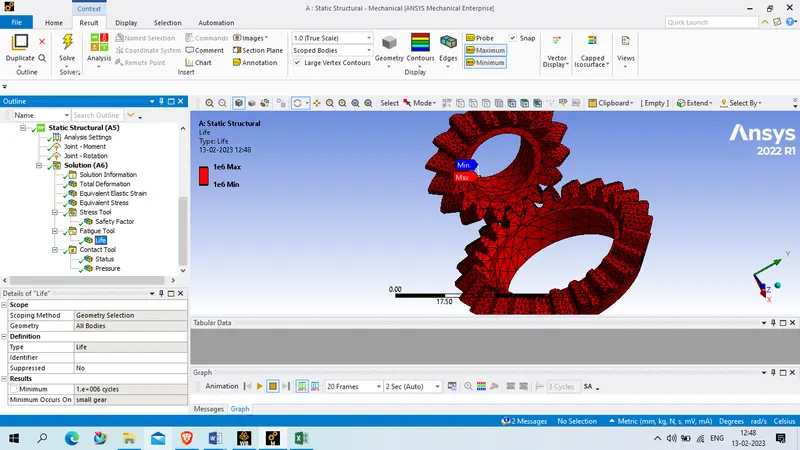
Life
for grid dependency test we used parametric test
for input we select mesh element size, and for output we used minimum , maximum and average deformation , minimum , maximum and average equivalent stress, and minimum maximum and average equivalent stress.
STrain
STress
Result :
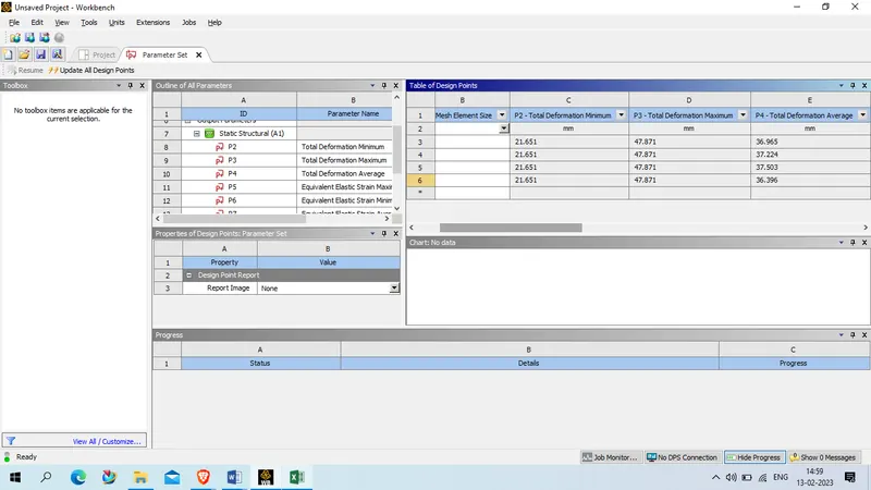
The total deformation for 5 cases are compared below
| Mesh element size (mm) | Teeth face mesh size (mm) | Minimum (mm) | Maximum (mm) | Average( mm) |
| 6 | 2 | 21.651 | 47.871 | 37.503 |
| 5 | 2 | 21.651 | 47.871 | 37.224 |
| 4 | 2 | 21.651 | 47.871 | 36.965 |
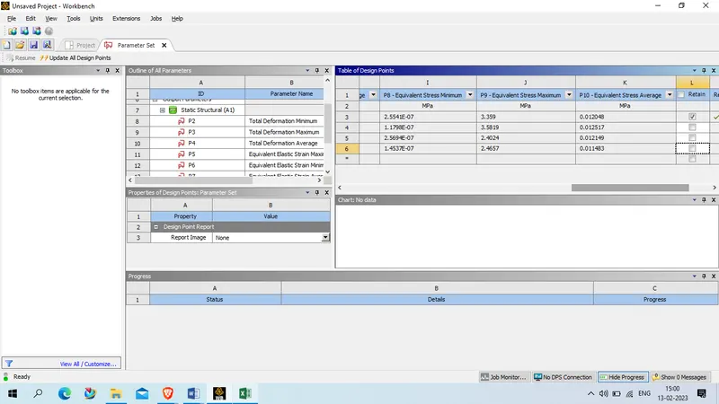
The equivalent stress for 5 cases are compared below
| Mesh element size (mm) | Teeth face mesh size (mm) | Minimum (Mpa) | Maximum (Mpa) | Average (Mpa) |
| 6 | 2 | 2.57E-07 | 2.4024 | 0.012149 |
| 5 | 2 | 1.18E-07 | 3.5819 | 0.012517 |
| 4 | 2 | 2.55E-07 | 3.359 | 0.012048 |
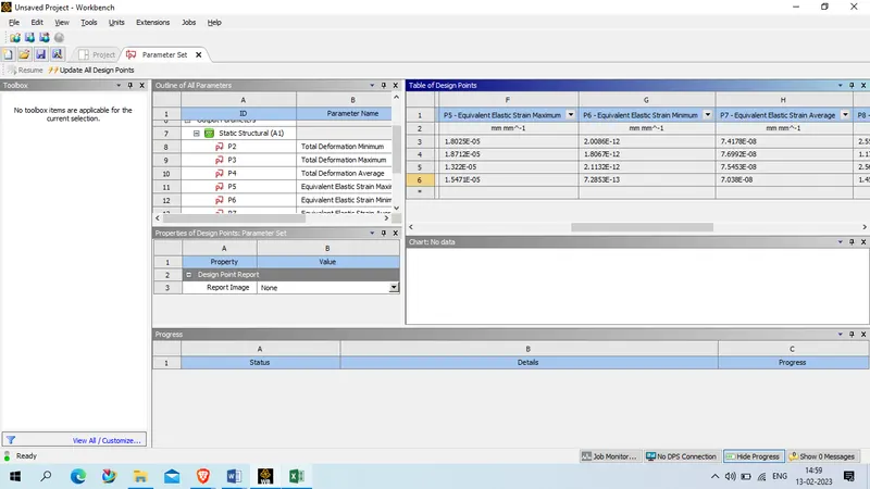
The equivalent strain for 5 cases are compared below
| Mesh element size (mm) | Teeth face Mesh size (mm) | Minimum | Maximum | Average |
| 6 | 2 | 2.11E-12 | 1.32E-05 | 7.45E-08 |
| 5 | 2 | 1.81E-12 | 1.87E-05 | 7.70E-08 |
| 4 | 2 | 2.01E-12 | 1.80E-05 | 7.42E-08 |
Conclusion :
It is observed that no change is obtained for the Total Deformation for all the cases and remained at 47.87 mm (Max)
as expected from grid dependency test, as we improove the mesh size from course to fine result get acurate,
as we see from maximum stress and maximum strain we can observed 6 mm and 5 mm have too much difference , and in comparison on 5 mm and 4 mm result we cam see this have negligible difference
Max stress 6 mm is 2.4024 Mpa, in 5 mm 3.5819, the difference is 32.9 % which is huge
while maxz stress in 5 mm 3.5819 and max stress in 4 mm 3.359, the dirrerence is only 6 %.
while comparing strain we can see in 6 mm and 5 mm mesh size have max difference whicle comparing 5 and 4 mm it have negligible differene .
If the mesh size is further reduced, it will only increase computational time. Therefore, it can be said that the optimal mesh size is 4mm.