Week 2 Bevel Gear Challenge
1) GRID dependency means size of element used for analysis.
Size of grid is playing an important role in accurate values of solution in analysis. We can use coarse or medium or fine type of elements in meshing. If we want very accurate results or accurate stress & strain values we go with fine meshing.
We know that each elements have some nodes and each node have 6 dof. And number of elements is more in fine meshing than the medium and coarse meshing. As elements increases the nodes increases, as nodes increases the dof also increases. So, the time required to solve the dof is increases in fine meshing. So, we cannot always go fine meshing.
We can go with medium or coarse meshing if we want to reduce the time solving. But I cannot give very accurate results as fine meshing.
Then how to decide the which type we consider for our analysis?
Here we compare the results with experimental values and analytical method then we decide which type of meshing required. And some times we chose the grid on basic of our computer. Because some time, if we go large elements, our computer will crash due less graphics. We also choose the grid size on basic of types of analysis.
Uses of GRID
1. To get accurate results.
2. To reduce the time of solving.
3. To simplify the analysis.
2) we are performing to grid dependency test to check how the grid effect the results of bevel gears analysis.
1. To start the analysis. We have drawn the static structure analysis into the work place.
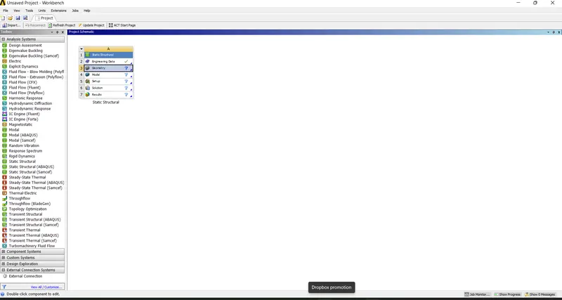
2. Double click on the engineering materials and add structural steel.
3. Now double on the geometry and import the model. Now check the geometry. We found that shaft holding part of gear has no use in analysis because we focus at the gear teeth. Remove the unwanted part in the gear in the spaceclaim.
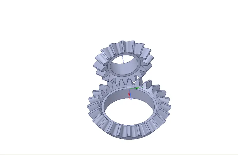
4. Open the model by double click on the model. After opening the model interface just check weather our model loaded or not.
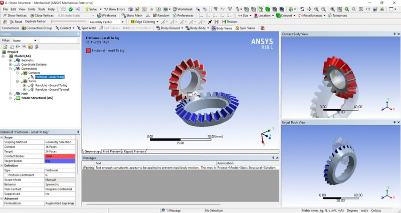
5. Go to connection and give the connection as required shown below. And change formulation method to augmented lagrange
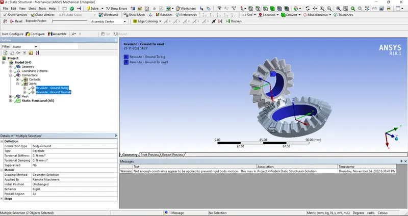
6. Now go to mesh setting. put default size as 5 mm. and generate the meshing.
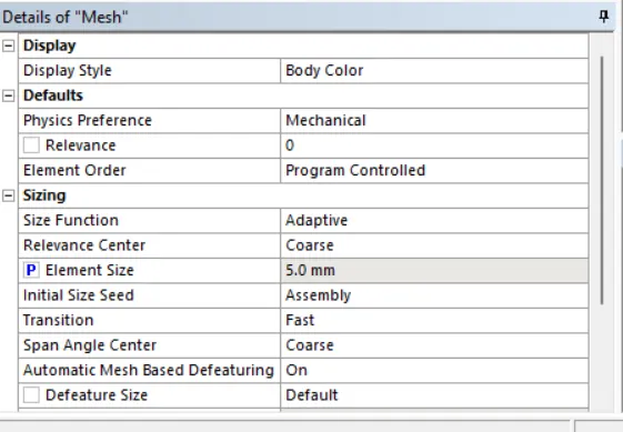
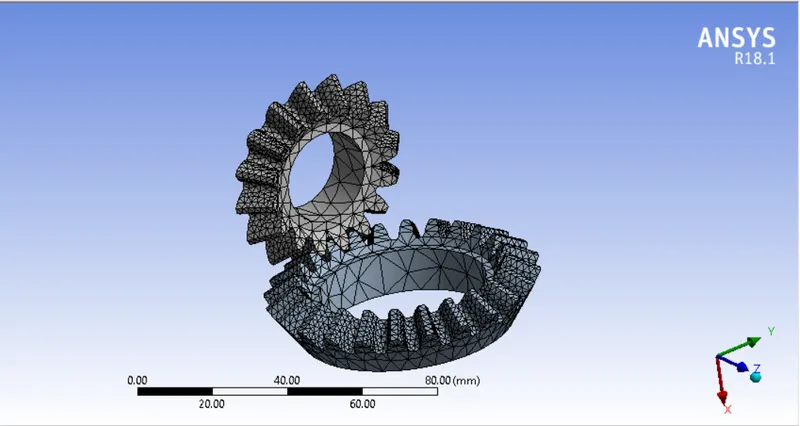
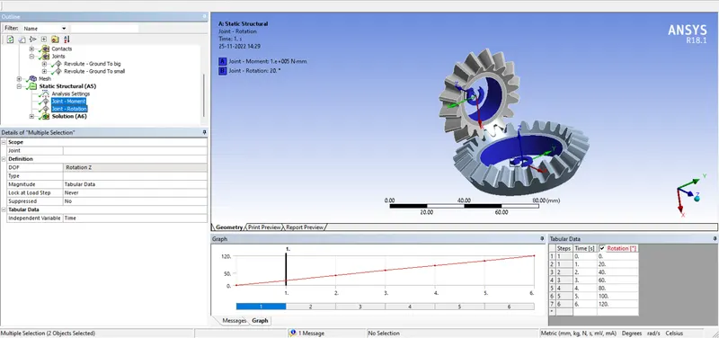
7. After completing the meshing. Go to analysis setting now change the steps to 6 and select the all 6 steps at a time. And change the initial time minimum and maximum time as shown below.
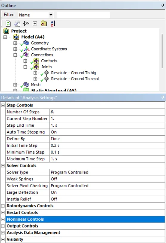
8. Create the joint loads small gear as revolute and big gear to moment with 100 N-mm.
9. Crete the solution which we required to find, like stress and strain.
3) Run the solution.
We can see the force convergence. The force convergence means we can plot force between the gears when meeting. We can see the how the force varies with the time in mating.
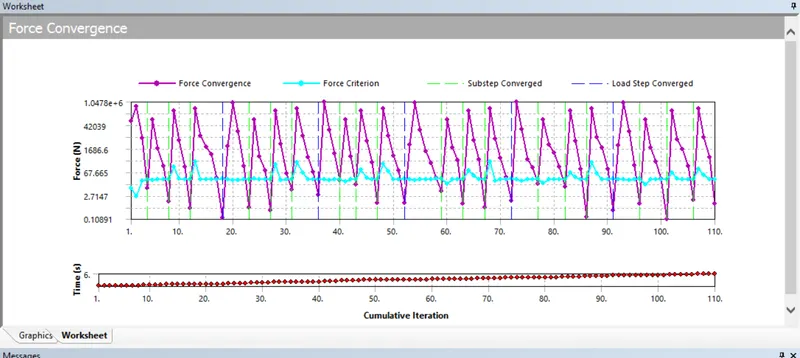
Here we can see stress and total deformation of the gears.
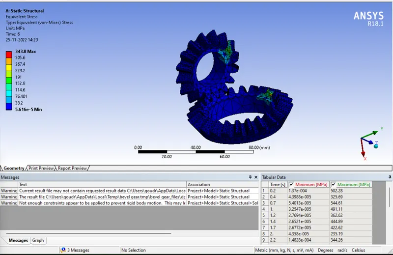
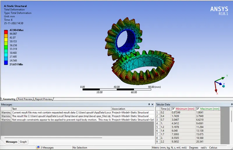
We could see that maximum stress develop in the 343.8 MPa and maximum total deformation is 47.904 mm and minimum total deformation is 21.651.
Grid dependency test:
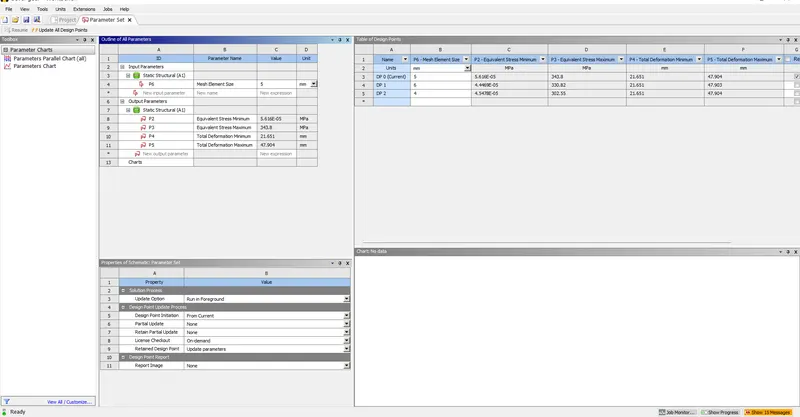
We can set the parameters for meshing length and check the check the stress and total deformation.
After ging the parameters set click on update the project. After loading the solution, we can see the stress and deformation values in the same page.
OBSERVATION:
In case of stress
For the mesh size 4 mm we got 302 MPa,
For the mesh size 5mm we got 348 MPa,
For the mesh size 6 mm we got 330.82 Mpa.
In case of deformation
For the mesh size 4 mm we got 47.904 mm maximum deformation,
For the mesh size 5mm we got 47.904 mm maximum deformation,
For the mesh size 6 mm we got 47.903 mm maximum deformation.
conclusion:
From the above observation we conclude that the mesh size of 5 mm give the good results and less time to solve compared to the 4 mm mesh