Week 2 Bevel Gear Challenge
Aim :
To perform analysis and compare the results for the given different mesh size of same material using ANSYS software.
Objective :
The main objective is to apply given three different element size for same material and observe the difference in solution values.
We solve the analysis for three different element size 4, 5, 6 and compare the results that is asked to solve.
Given model :
Bevel gears are used in differential drives, which can transmit power to two axles spinning at different speeds, such as those on a cornering automobile. Bevel gears are used as the main mechanism for a hand drill.
Bevel gears are used to transmit rotational motion at right angles, whereby the two axis of the gears intersect. This type of gear is therefore often built symmetrically. The movement consists of rolling without sliding of two bevels.
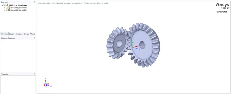
The Grid dependency test in Finite element analysis is a process used to find the optimal size of elements generating a difference in the numerical results based on the evaluation of various results. We define the grid as element and nodes and based on the mesh element size the mesh gets refined so with respect to the refinement we absorb change in values in solution part. The values may be a minute change from the above or below value from the number which we choose.
Formula: Augmented Lagrange.
This method is also a penalty-based method. It uses the same equation for solving but has an extra augmentation constant, λ(lambda). Because there is an extra term in the equation, the contact force becomes less sensitive to the stiffness. So, there will be lesser penetration at the contacts. Hence, this formulation is preferred more.
𝑭𝒏𝒐𝒓𝒎𝒂𝒍 = 𝒌𝒏𝒐𝒓𝒎𝒂𝒍 × 𝒙𝒑𝒆𝒏𝒆𝒕𝒓𝒂𝒕𝒊𝒐𝒏 + 𝝀
Procedure :
- We perform Structural analysis here so we select and place it in the main screen.
- We have to add the material and material data in engineering tab.
- Here the material is not mentioned so here we take default material structural steel for analysis.
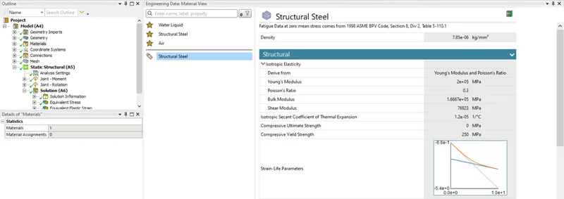
- Next step we have to import the geometry in geometry tab.
- In this model the geometry is to be modified by removing the additional part which is not required for our analysis.
- Geometry modification is done by using Ansys spaceclaim software.
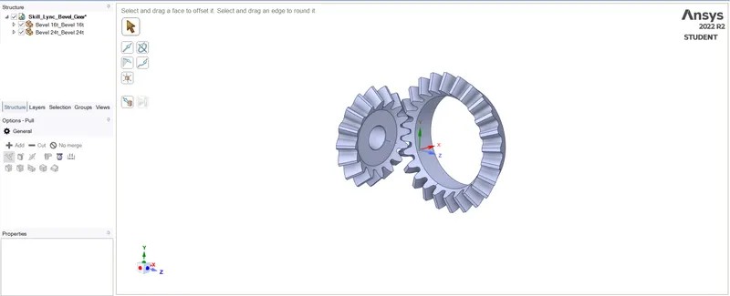
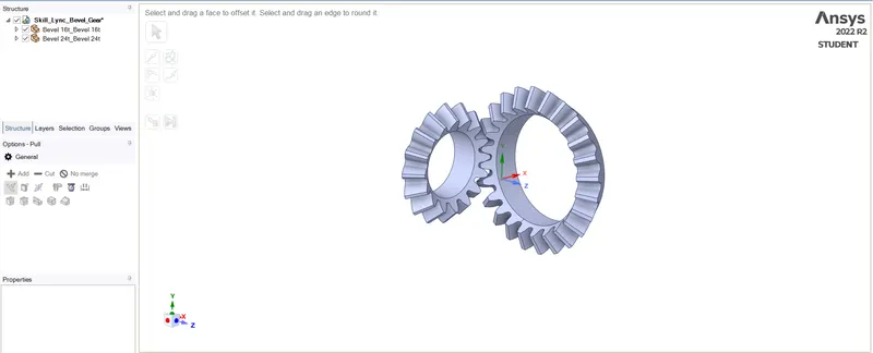
- These operations are performed in work bench and for model tab we move to mechanical setup screen.
- In mechanical window we add data which is required to solve the process.
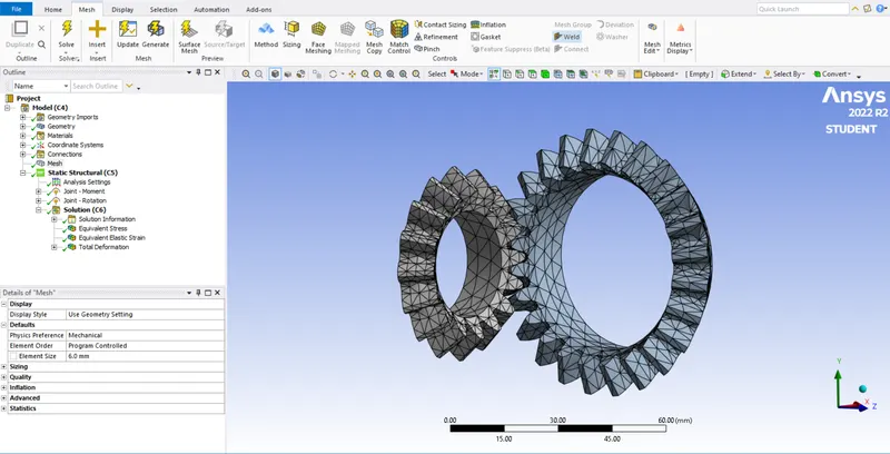
- For mesh we change the element size to be 4mm, 5mm and 6mm. In student edition we have limitations for nodes and elements.
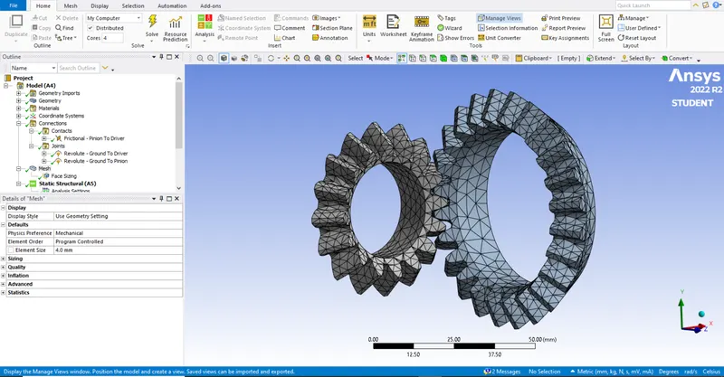
- We choose connections option to select the faces of contact between both gears.
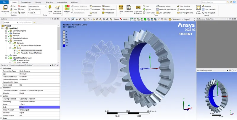
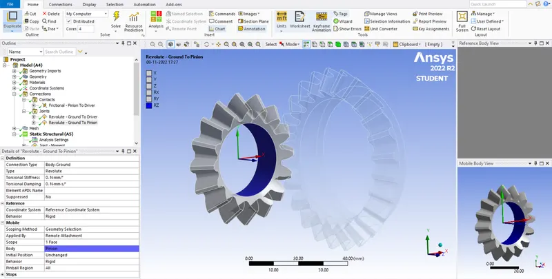
- In contacts we define the connection type in joint option as body to ground and the type as revolute. Through scope we fix the co- ordinates. For both the gears same method.
- We define the type of contact as Frictional contact.
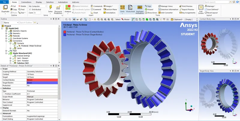
- We change the behaviour to Symmetric.
- We define the formulation as Augmented Lagrange.
- In geometry modification we change the interface treatment to adjust to touch.
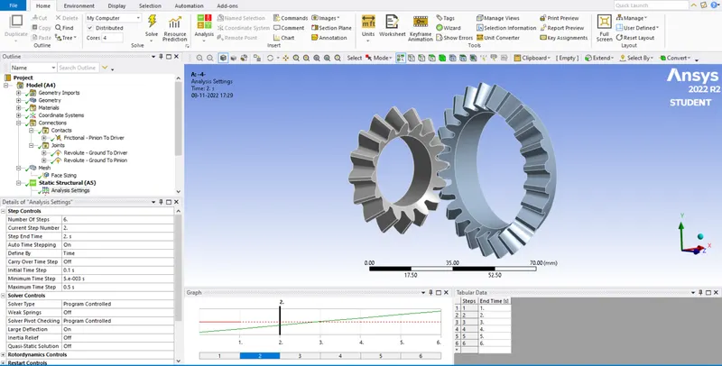
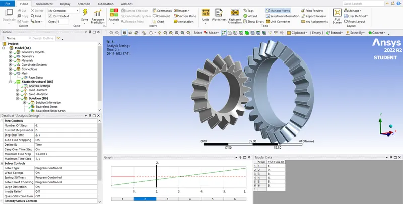
- In static structural we choose analysis settings there we add the number of steps data and switch on the large deflection and auto time stepping. Which is defined by time.
- Add data like initial time step, minimum time step and maximum time step.
- In static structural we insert joint load for both the gears in that degree of freedom and magnitude values are added for the rotation of gears.
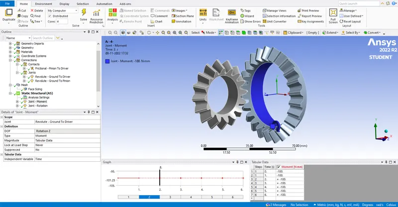
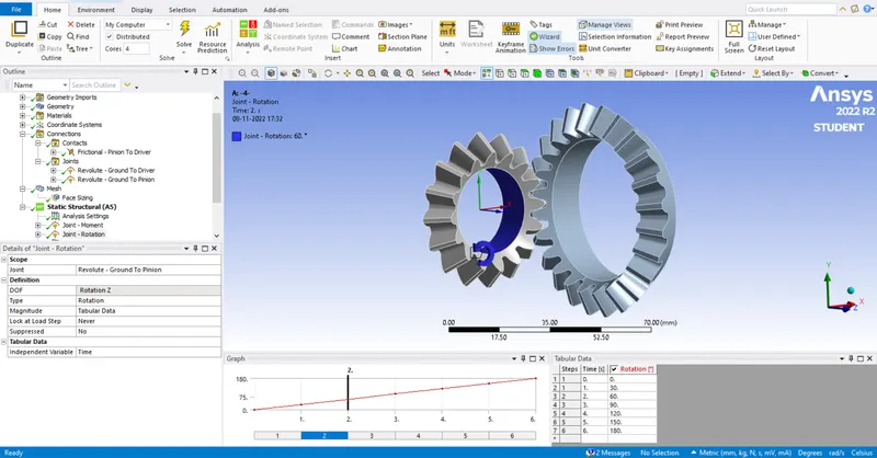
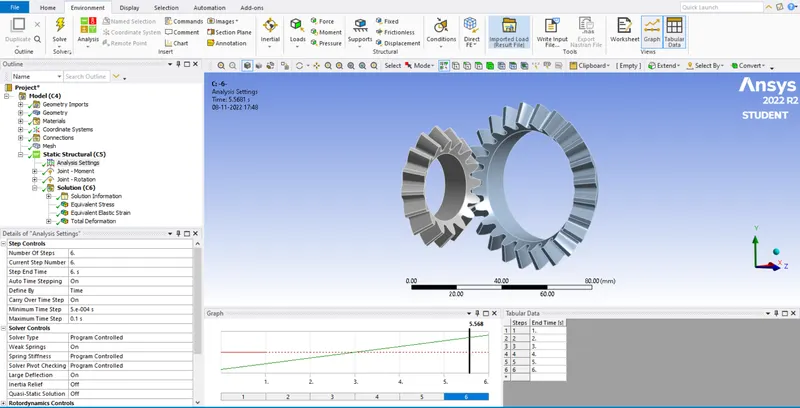
- In solution tab we choose three options which is asked to do analysis for they are,
- Equivalent stress (Von-Mises stress),
- Equivalent elastic strain,
- Total deformation.
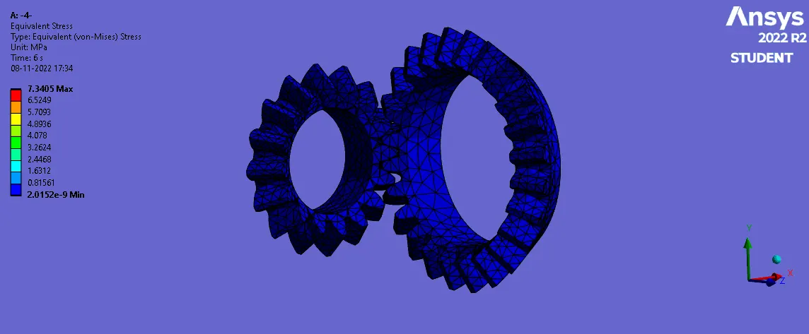
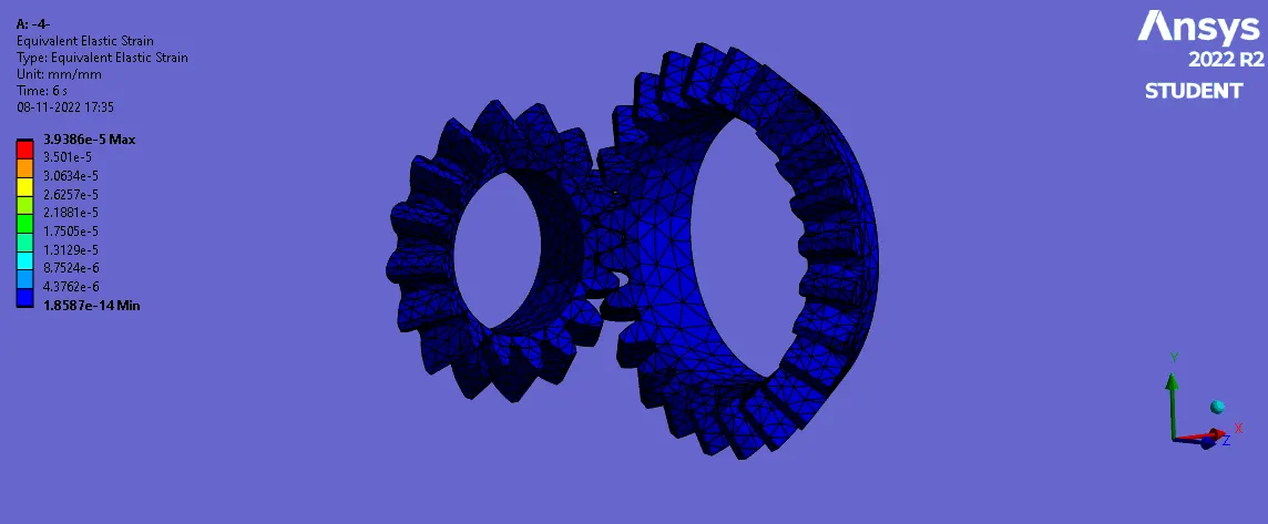
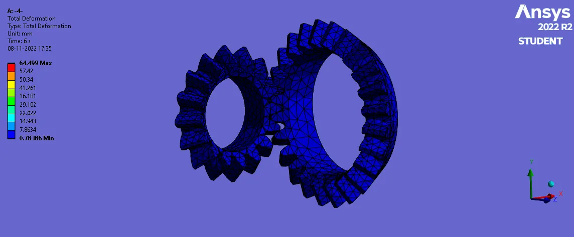
Analysis and report with screenshort :
Mesh size : 4mm,
Mesh size :5mm,
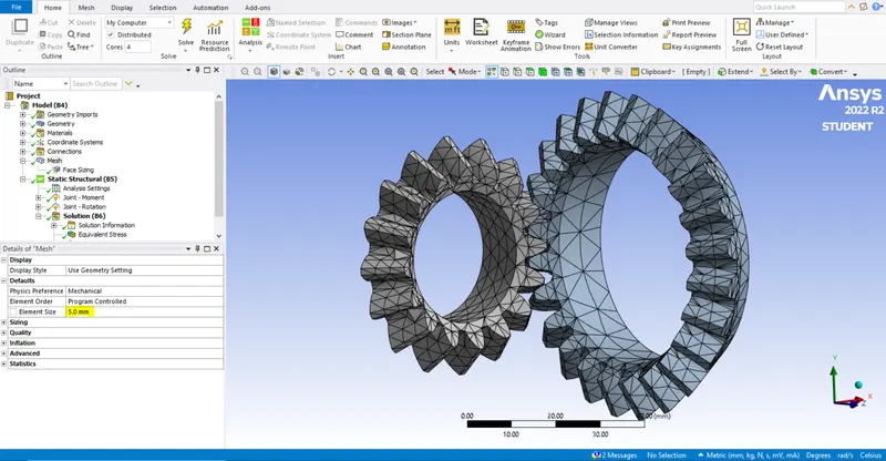
Mesh size : 6mm.
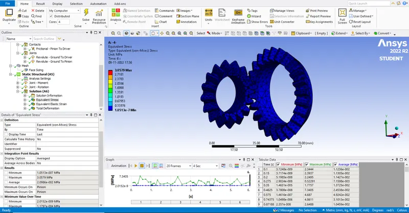
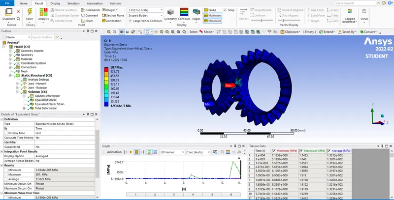
Equivalent stress (Von-Mises stress) :
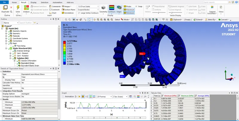
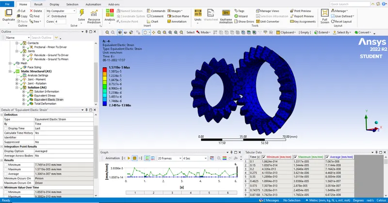
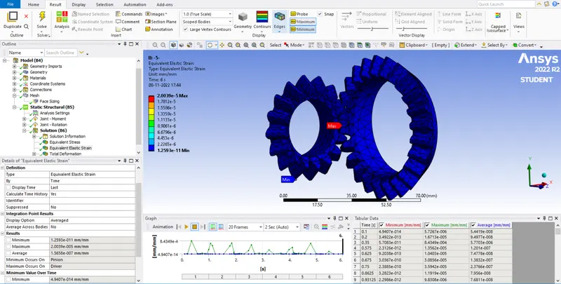
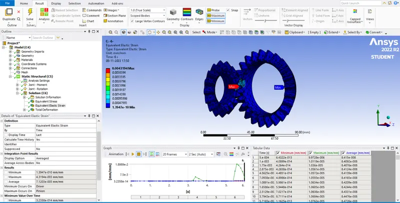
Equivalent elastic strain :
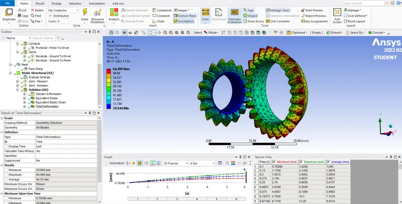
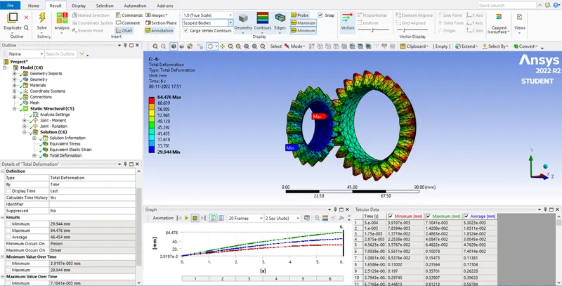
Total deformation :
Conclusion :
| Mesh / Solution | Equivalent(Von-Mises stress) | Equivalent elastic strain | Total deformation |
| Mesh size = 4mm | 3.0579Mpa (max) | 1.5719e-5 mm (max) | 64.499 mm (max) |
| Mesh size = 5mm | 3.2375Mpa (max) | 2.0039e-5 mm (max) | 64.499 mm (max) |
| Mesh size = 6mm | 587Mpa (max) | 0.0043194 mm (max) | 64.476 mm (max) |
From the above table values it is clear with respect to grid dependency test the stress value comparirision between 5mm and 4mm mesh are equal. To attain the same value we did one more analysis which consumes more time to do analysis and results. In industry point of view the additional time consuption for the same result is not reccomended.
With help of grid dependancy test we have learnt that the for a minute change in values performing one more analysis will consume more time and effort for analysis and results.
Result :
We haved performed the mesh for differnt size and compared the solution for the given Bevel gear model successfully by using ANSA software.