Week 2 Bevel Gear Challenge
Stress Concentration on a Bevel Gear
I. GRID DEPENDENCY TEST:
Grid dependency test is to investigate how the solution depends on the grid size by simulating with a refined mesh that is finer, and higher in the accuracy of the result but with additional cost on computation time and computational power. Since solutions are interpolated at the nodes to get an approximate result, the higher the number of nodes and elements, the higher the computational time and power required to complete the simulation.
So, the grid dependency test helps in determining optimal mesh size where the accurate result could be obtained keeping in the mind the cost of time and power. Since the result obtained are approximate,
Refining mesh further would result in negligible percent change is the result but only increase the computational cost.
The most fundamental method of checking the mesh quality is to refine a mesh until desired output result/data does not change significantly with each refinement. In the Grid dependency test, analysis begins with a coarse mesh and it is refined to a finer mesh for each run until the results are significantly close and dependent on the grid size is not needed
There are different mesh refinement techniques used which have pros and cons for each and some are dependent on the FEA Engineer’s expertise. These techniques include Varying the element size (Increase\decrease), Global/Local Adaptive mesh refinement, manual refinement of the mesh, Time adaptive mesh refinement, wavelength adaptive mesh refinement, etc.
II. OBJECTIVES:
To carry out a Gear Dependency Test using Static Structural Analysis on Bevel Gear for the given three cases which use different mesh sizing for the spur gear and determine the Equivalent stress, deformation, and Equivalent Elastic strain.
CASE-1 – 6mm:
For Case-1, Static Structural Analysis was carried out with the given Bevel gear model. The mesh/element size used for this analysis was 6mm and the analysis was carried out using ANSYS Mechanical Enterprise. The model for case-1 was imported to ANSYS Workbench software and is shown in the figure below.
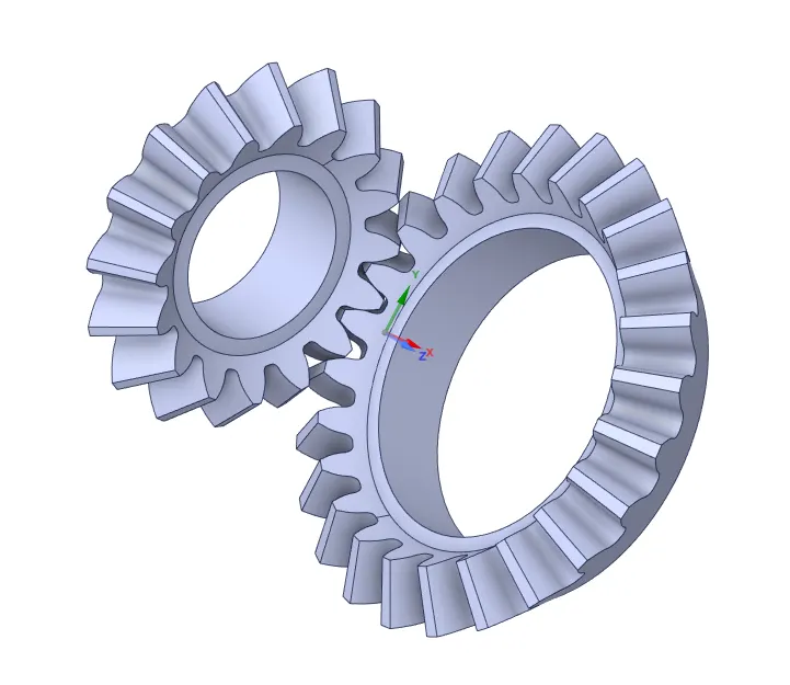
Fig.1 Case-1 Bevel Gear Model
Later the material (STRUCTURAL STEEL) was assigned and the material and its properties used for this analysis are specified below for both gears.
|
Material |
Structural Steel |
|
Density |
7.85e-6 kg/mm3 |
|
Young’s Modulus |
2e+5 MPa |
|
Thermal Conductivity |
0.0605 W/mm°C |
|
Specific Heat |
4.34e+5 mJ/kg°C |
|
Tensile Yield Strength |
250 MPa |
|
Tensile Ultimate Strength |
460 MPa |
Then the model was meshed in ANSYS Mechanical Enterprise with an element size of 6mm and using Tetrahedrons were employed. And Face Sizing of 1.75mm element size was assigned to the 40 tooth faces of both gears i.e., 16 faces of the Small gear and 24 faces of the big gear.
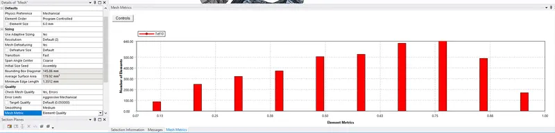
Fig.2 Element Quality
A mesh metric that identifies elements according to their quality was employed and it can be seen that the elements of the lowest quality are minimal. Most of the elements have very high quality in the range of 0.63 to 0.88. Hence, the mesh is of acceptable quality. The meshed model is shown below.
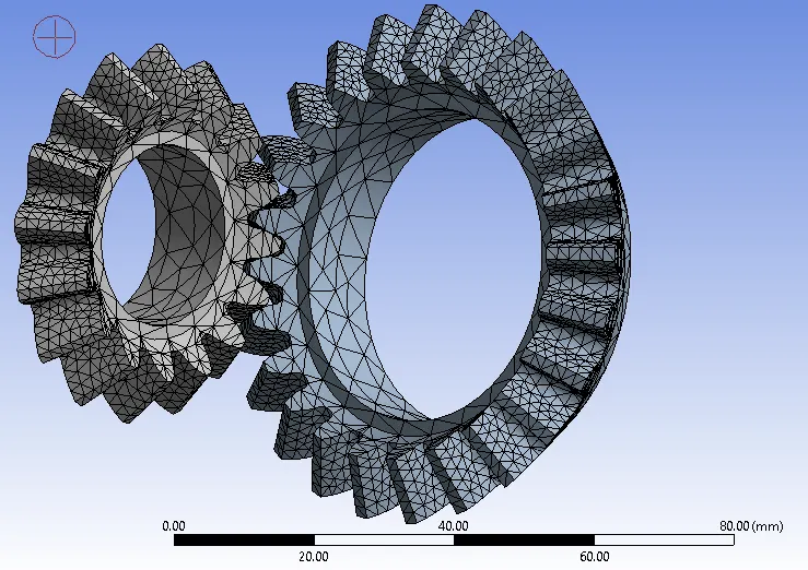
Fig.3 Meshed Model – 6mm element size
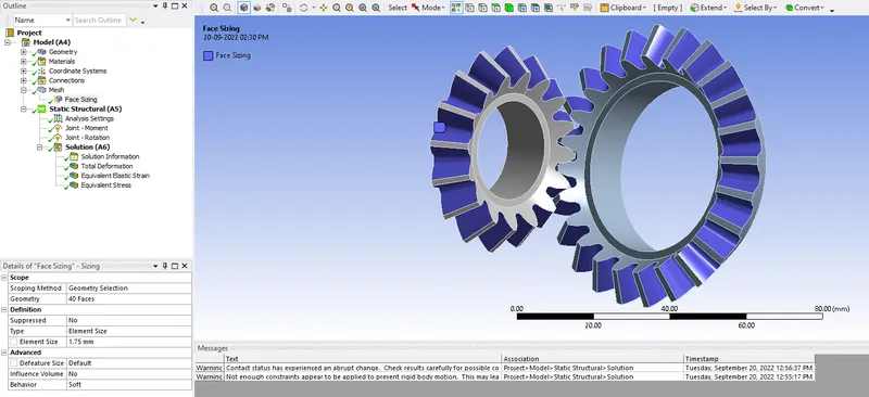
Fig.4 Face Sizing of 1.75mm
Then Contacts were provided with FRICTIONAL type, SYMMETRIC behavior and using AUGMENTED LAGRNGIAN formulation method and ADJUST TO TOUCH Interface Treatment. Later REVOLUTE Joints were assigned to both the gears with BODY-GROUND Connection Type. The Simulation is then run with the applied Joint Loads of i) ROTATION for Small gear for 120-degree rotation angle with an increment of 20 degrees for each step and ii) MOMENT for Big gear with a magnitude of 100 Nm for 6 number of steps for the entire analysis run. It was ensured that both the gears rotated in Opposite Directions and simulation was carried out and results were obtained for Equivalent Stress, Total Deformation, and Equivalent Elastic Strain where obtained. Analysis Setting was provided with 6 number steps and data for all 6 steps with AUTO TIME STEP, LARGE DEFORMATION – ON, Minimum and Maximum Time Step as 0.05s and 0.4s with Initial time step of 0.2s.
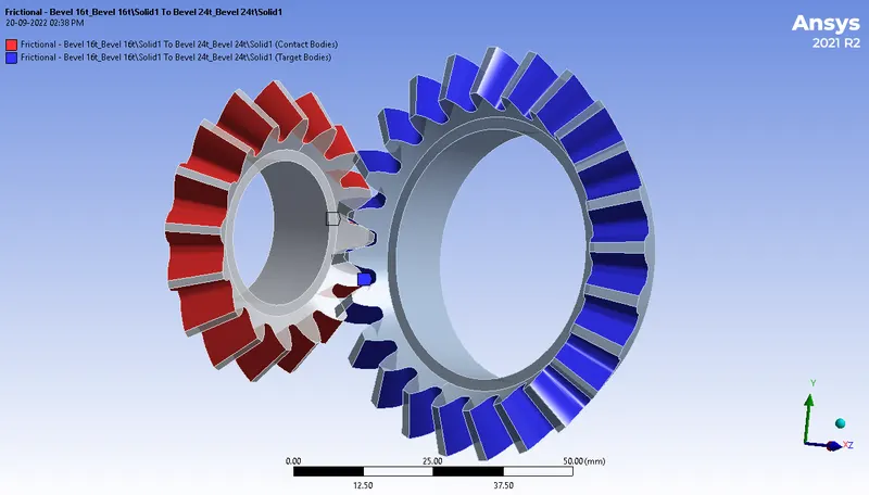
Fig.5 Frictional Contact
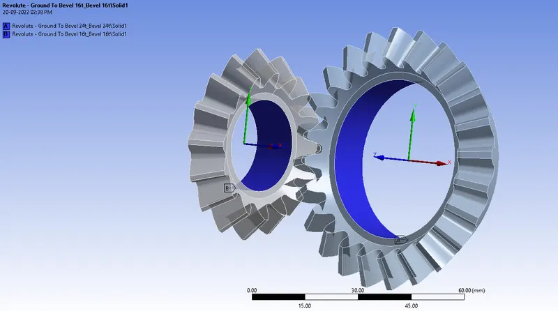
Fig.6 Revolute Joint
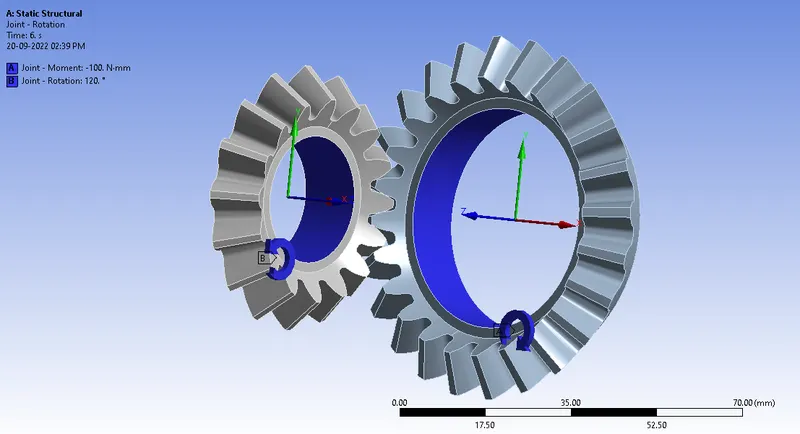
Fig.7 Load Applied (Rotation and Moment)
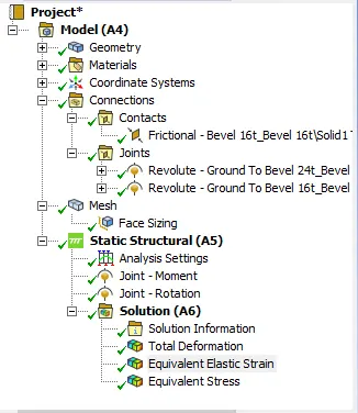
Fig.8 Case Setup.
CASE-2:
For Case-2, Static Structural Analysis was carried out with the given Bevel gear model. The mesh/element size used for this analysis was 5mm and the analysis was carried out using ANSYS Mechanical Enterprise. The material used for Case-2 is also Structural Steel. The same contacts and load used in Case-1 were used in Case-2 also with only a change in mesh size of the Bevel Gear(unchanged Face Sizing). Then the analysis was run and results were obtained. The meshed model for Case-2 is shown below.
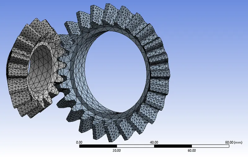
Fig.9 Meshed Model – 5mm element size
CASE-3:
For Case-3, Static Structural Analysis was carried out with the given Bevel gear model. The mesh/element size used for this analysis was 4mm and the analysis was carried out using ANSYS Mechanical Enterprise. The material used for Case-3 is also Structural Steel. The same contacts and load used in Case-1 were used in Case-3 also with only a change in mesh size of the Bevel Gear(unchanged Face Sizing). Then the analysis was run and results were obtained. The meshed model for Case-3 is shown below.
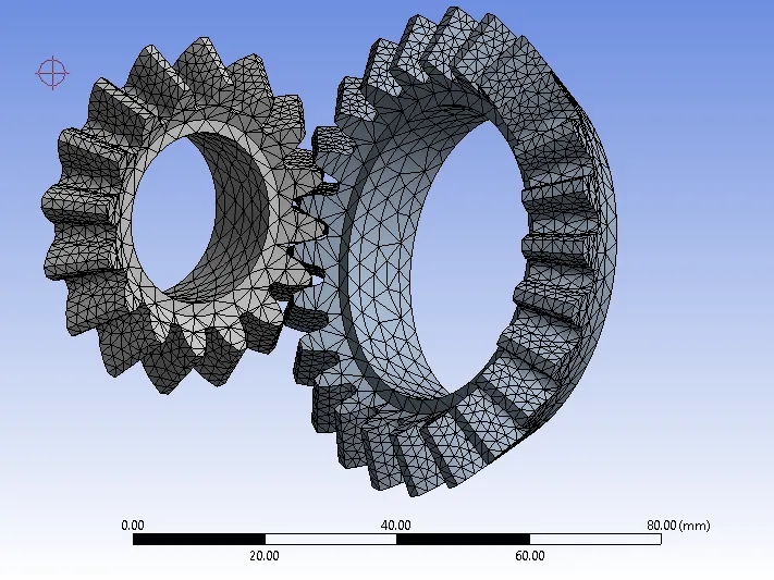
Fig.10 Meshed Model – 4mm element size
SETTING PARAMETERS:
After the first Case-1 simulation was run and results were obtained, Parameters were set to obtain the results for Case-2 & 3 as only the mesh sizing is different and all other output data to obtain remains the same. So, the Input Parameter was set to Element Size and the Output Parameters were set to Equivalent Stress (Maximum), Total Deformation (Maximum), and Equivalent Elastic Strain (Maximum).
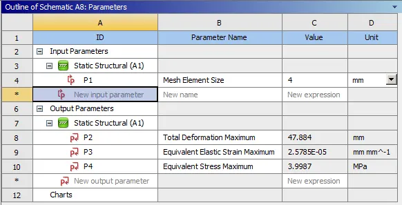
Fig.11 Input and Output Parameters set
Once the required input and desired output parameters were set and assigned will input data(i.e., Element Size), then the simulation was run to Update all the Design Set Points.
RESULTS:
The results obtained from the Parameters were tabulated below.

Fig.12 Parametric set Result Data
In the above figure, DP0 with a Mesh Size of 0mm representing the DEFAULT Mesh Size was used and the simulation was run. The no. of nodes and elements for each case is tabulated below.
|
Case |
Mesh Size [mm] |
No. of Nodes |
No. of Elements |
Face Sizing [mm] |
|
1 |
6 |
25824 |
13809 |
1.75 |
|
2 |
5 |
26345 |
14090 |
1.75 |
|
3 |
4 |
17993 |
15056 |
1.75 |
The Total Deformation, Equivalent (Von-Mises) Stress, and Equivalent Elastic Strain data were obtained and MAXIMUM AND MINIMUM DATA on the desired output for the ENTIRE CYCLE is tabulated below.
|
Case |
Mesh Size [mm] |
Total Deformation [mm] |
Equivalent (Von-Mises) Stress [MPa] |
Equivalent Elastic Strain [mm/mm] |
|||
|
Max. |
Min. |
Max. |
Min. |
Max. |
Min. |
||
|
1 |
6 |
47.884 |
0.90739 |
6.1459 |
8.2919e-9 |
4.1082e-5 |
1.147e-13 |
|
2 |
5 |
47.884 |
0.90739 |
5.5190 |
1.2350e-8 |
3.2083e-5 |
1.380e-13 |
|
3 |
4 |
47.884 |
0.90739 |
5.5385 |
7.5086e-9 |
2.8526e-5 |
8.477e-14 |
The Total Deformation for all the three cases obtained from the analysis is shown below.
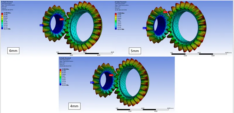
Fig.13 Total Deformation Contour Plot
The Equivalent (Von-Mises) Stress for all three cases obtained from the analysis is shown below.
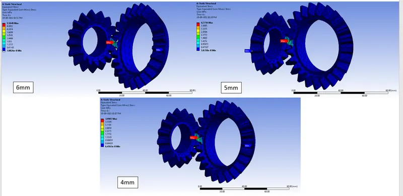
Fig.14 Equivalent Stress Contour Plot
The Equivalent Elastic Strain for all the three cases obtained from the analysis is shown below
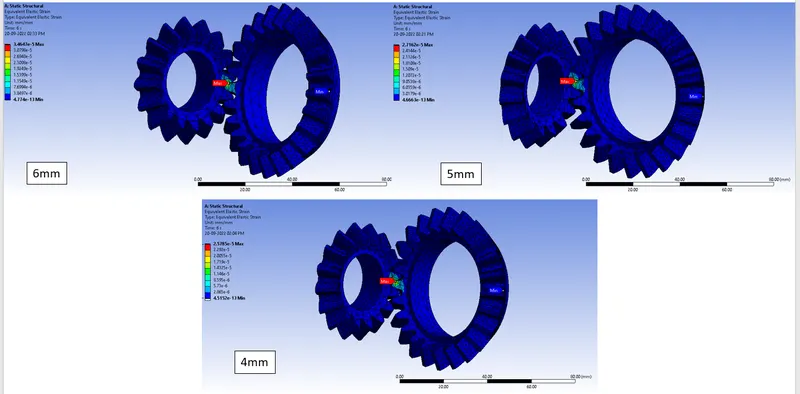
Fig.15 Stress Intensity Contour Plot
The Total Deformation graph/table plot is shown below.
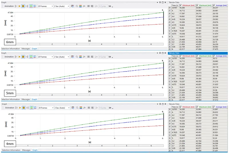
Fig.16 Total Deformation Table Plot
The Equivalent (Von-Mises) Stress graph plot is shown below.
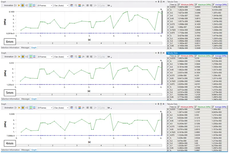
Fig.17 Equivalent Stress Table Plot
The Equivalent Elastic Strain graph plot is shown below
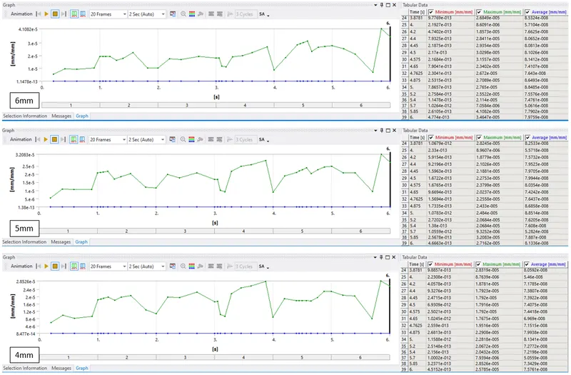
Fig. 18 Stress Intensity Table Plot
CONCLUSION:
The analysis was run successfully for all three cases and results were obtained and tabulated. A Grid Dependency test has been performed and from the Parametric Set table (Fig.12), we can conclude that by performing a grid dependency test on bevel gear by varying the global size of the mesh, we achieve much better accuracy in the result. We can observe that as the mesh is refined from e.g 5mm to 4mm as we achieve a better approximation of the result for equivalent elastic strain and equivalent stress, however, performing the simulation with further refining of the mesh would result in a very close approximation of the result but with very negligible change in the result with an additional on the computational power and time. So, element size of 4mm can be finalized.