Week- 5 - Solid meshing
3D Meshing for Plastic Component – Rear View Mirror
AIM:
To generate a 2D mesh for the given Rear View Mirror model by taking Mid Surface for each component present in the model after clearing the geometrical errors present in the model followed by meshing with the given Quality Criteria.
PROCEDURE:
The following diagram provides the flow chart of the work being progressed for meshing the given Rear View Mirror model.
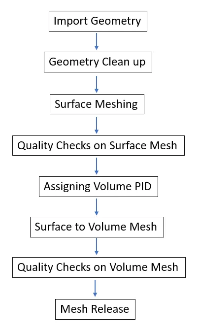
Fig.1 Flow Chart
Geometry Import: First the Rear View Mirror model has been imported to the Ansa software and preliminary checks on the geometry have been carried out. The preliminary checks include the geometry error checks. If any errors present in the model were cleared later. Figure 2 provides the topological/geometrical model imported into ANSA.
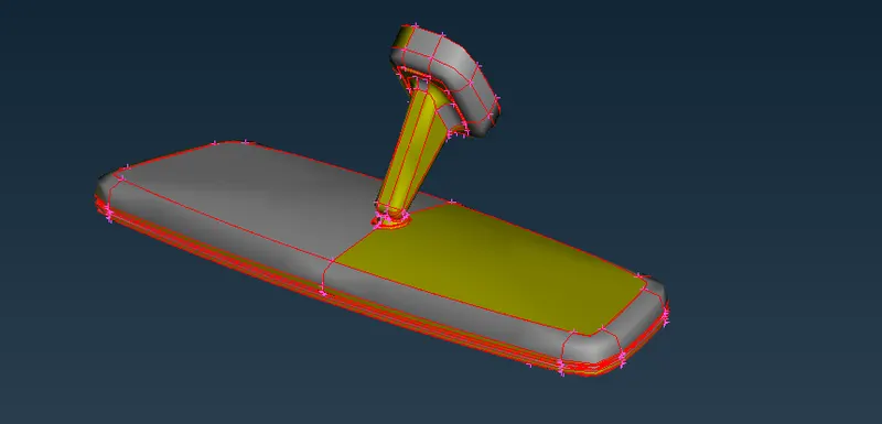
Fig. 2 The Rear-View Mirror model imported into ANSA Software
Geometry Clean-up: The geometrical errors present in the model have been cleared and the below figure provides a visual aid for the cleared geometry.
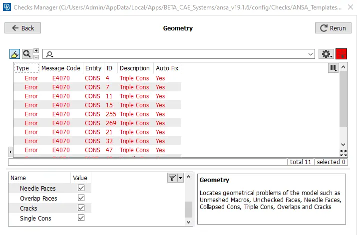
Fig. 3 Geometrical Error Check made on the model.
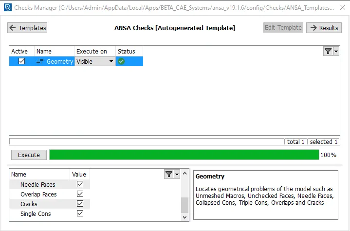
Fig. 4 Geometry Errors cleared.
The model has been checked and cleared for geometrical errors. Figure 4 shows that the given model is free from geometrical errors. After that orientation of the model has also been carried out.
Surface Meshing: After Mid Surface Extraction, meshing has been carried out on the surface with the following mesh parameters shown in figure 5.
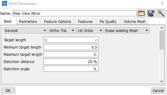
Fig. 5 Mesh Parameters.
Figure 6 shows the mesh created on the surface.
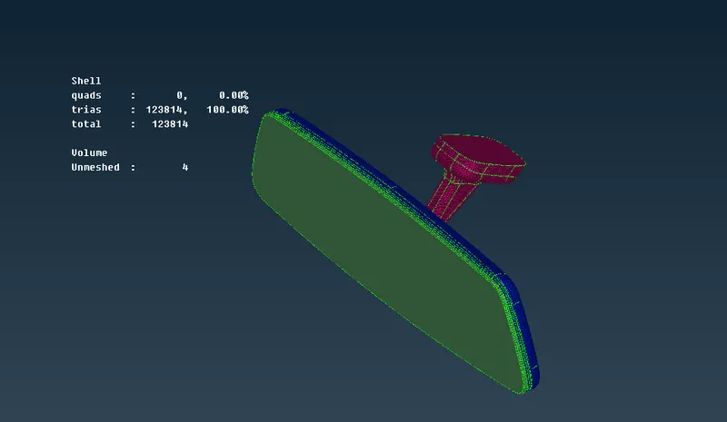
Fig. 6 Surface Meshed.
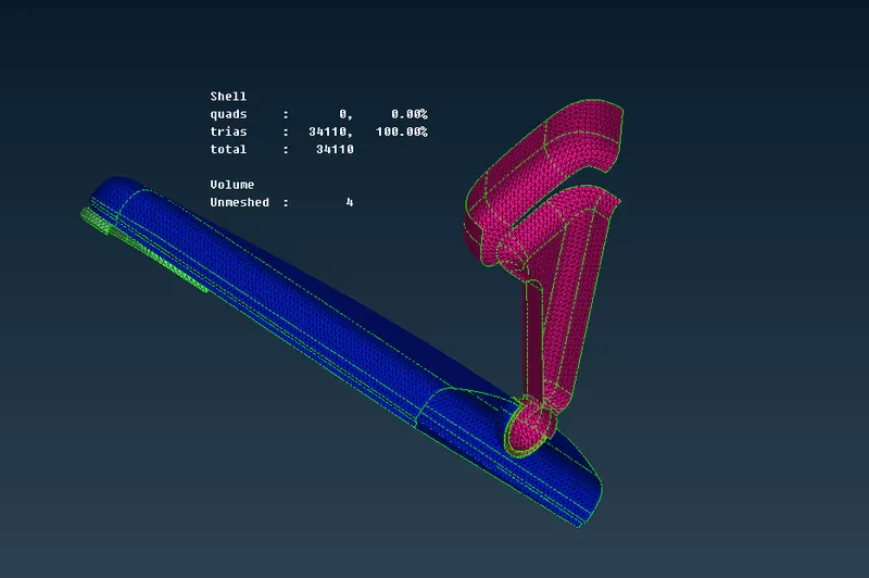
Fig. 7 Cross Section - Surface Meshed.
Surface Mesh Quality Checks: After surface meshing, quality checks have to be performed and the mesh should be free from quality errors. Figure 8 shows the Quality Criteria set for the given model.
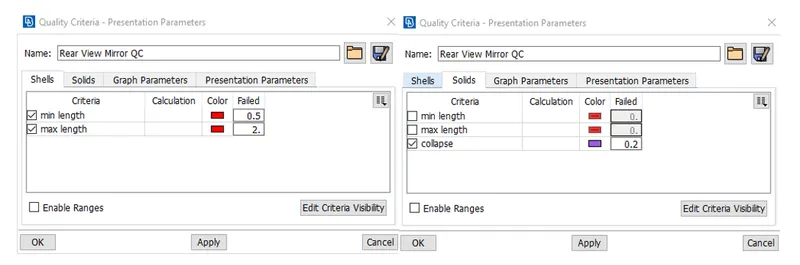
Fig.8 Quality Criteria Check.
The quality check was performed and quality errors were cleared. The mesh model free from quality error is shown the figure 9.
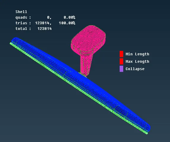
Fig. 9 Quality Checks performed on the mesh.
Assigning Volume PID: After clearing all the quality issues on the surface mesh, the volume has to be created for generating 3D mesh. So each component of the model has been declared as closed volume and separate PIDS were assigned as shown in figure 10.
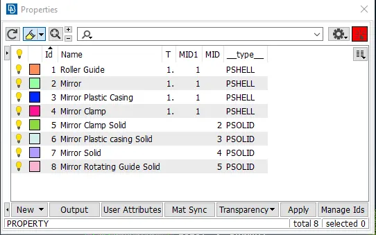
Fig. 10 Volume and PIDs assigned for each Component.
Surface To Volume Mesh Generation: After declaring closed volume, the Unstructured Mesh type is used. Under the Unstructured mesh tab, Tetra FEM or Tetra Rapid type of meshing can be selected. In this model, the Tetra FEM type meshing algorithm is used and 3D mesh is generated. Figures 11, 12 & 13 show the meshing algorithm type, 3D meshed model, and cross-section of the volume mesh.
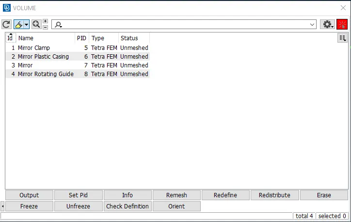
Fig. 11 3D Meshing Algorithm type.
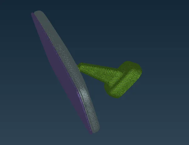
Fig. 12 3D Meshed Model.
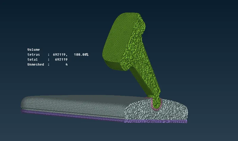
Fig, 13 Cross Section – Volume Meshed Model.
Quality Checks on the volume Mesh: After the volume mesh has been created, it has to be checked for the quality issue namely Tet Collapse. Figure 14 shows the volume meshed model is free from any given quality criteria.
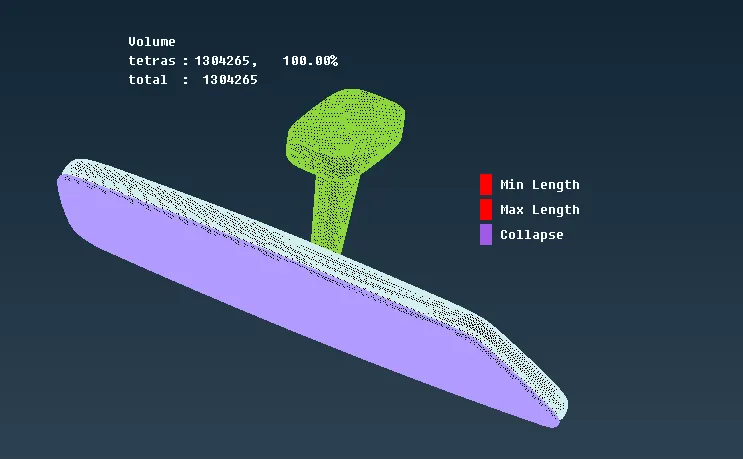
Fig. 14 Volume Quality Criteria checked.
Mesh Release: After the quality checks, the mesh elements were released from the geometry.
LEARNING OUTCOMES:
- Surface Tetra Mesh for any complicated geometry.
- Easy meshing with different Ortho Tria and Tria mesh options.
- Meshing of complex structure/components by splitting into many parts/cut portions.
- Good ortho tria mesh flows around openings or holes to capture it neatly.
- Assigning appropriate closed volume for 3D mesh Generation of each component.
CONCLUSION:
A 3D mesh is used for plastic components such as buttons, where it is challenging to extract mid-surface and assign appropriate thickness. In such areas, volume mesh will ease the work thus maintaining the original topology of the model.