Week 2 Bevel Gear Challenge
Grid Dependency Test
1)Write a few words on what a grid dependency test is and its use.
Grid dependency test is used to determine optimum/Best mesh size to find accurate solution keeping the computational time in mind .
- This process is followed until we get results that are optimum.i.e we get convergence.
- Further refining the mesh will not change the results as convergence is occured.
- One important thing about grid dependency is that as the mesh is refined, computational time also increases.
- So there should be limit upto where the mesh should be refined.
When modeling a problem using a finite element program, it is very important to check whether the solution has converged. The word convergence is used because the output from the finite element program is converging on a single correct solution. In order to check the convergence, more than one solution to the same problem are required. If the solution is dramatically different from the original solution, then solution of the problem is not converged. However, if the solution does not change much (less than a few percent difference) then solution of the problem is considered converged.
2)Perform a grid dependency test for the Bevel gear simulation for mesh sizes of 6,5 and 4 mm
PROCESS:
- Download the model and open into ansys geometry import
- Add the material in engineering data
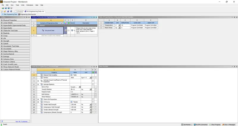
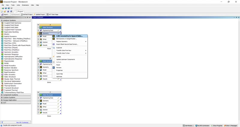
- Open the geometry to make changes in CAD
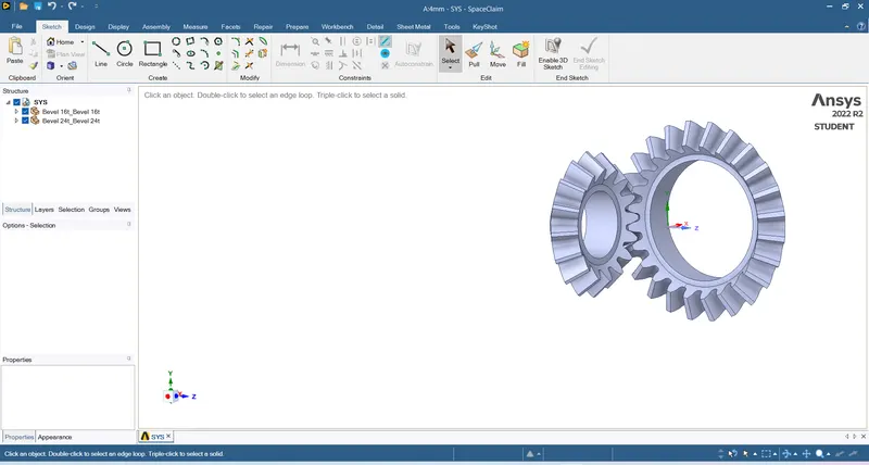
- Use the Circle & pull To remove the Excess material that would not be of interest
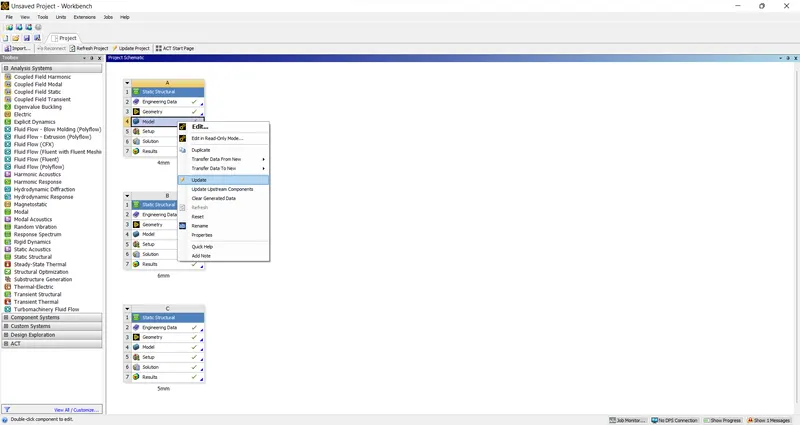
- Update & Open the model
- After opening check the material for both the gears in geometry section
- Keep the stifness behivaour as Flexiable as this is gone a rotate
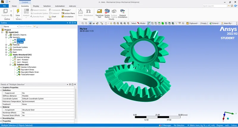
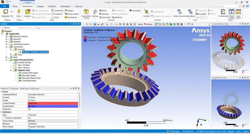
- Connections are made using contacts & Joints
- Select the faces in contacts between gears
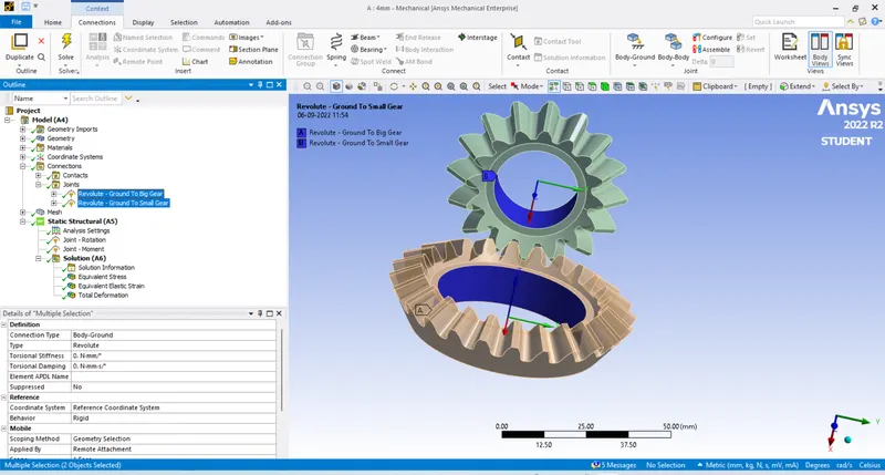
- In joints create body-Ground for both as they will rotate
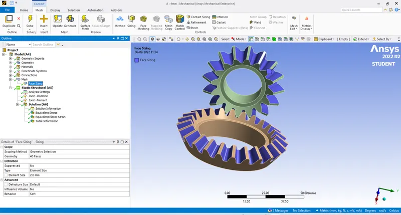
- Check for the mesh and keep the element size 4
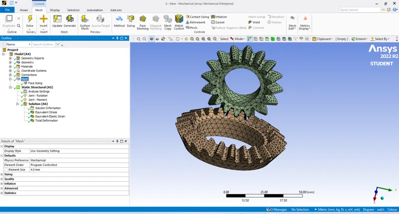
- Insert face sizing and enter the element size & select the faces
- For one gear give moment and for the other give rotation (Make sure that these are in different/opposite direction)
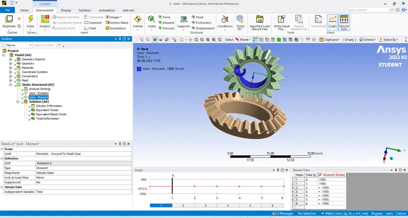
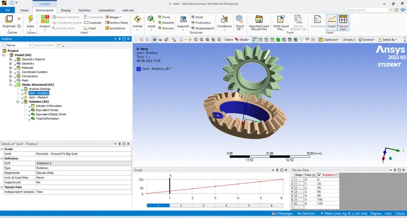
- Insert the required analysis Von-Mises stress, Equivalent elastic strain, and Total Deformation and go for solve
- For other 2 results we duplicate in the workbench
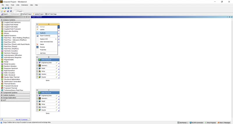
- Repeat the same process For given mesh sizes 5mm & 6mm
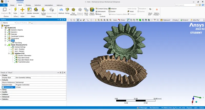
Clear the data before going for solve and proceed
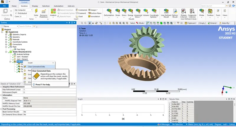
3) Solve for Von-Mises stress, Equivalent elastic strain, and Total Deformation using the previously mentioned mesh sizes.
RESULTS:
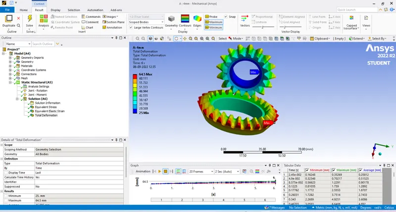
FOR 4MM
Von-Mises stress,
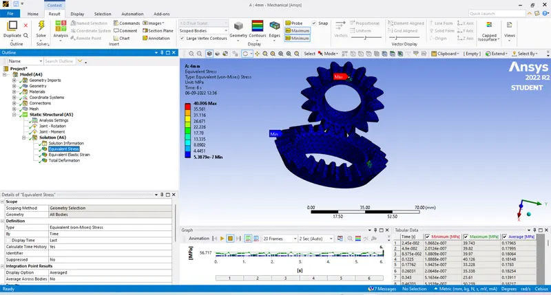
Equivalent elastic strain
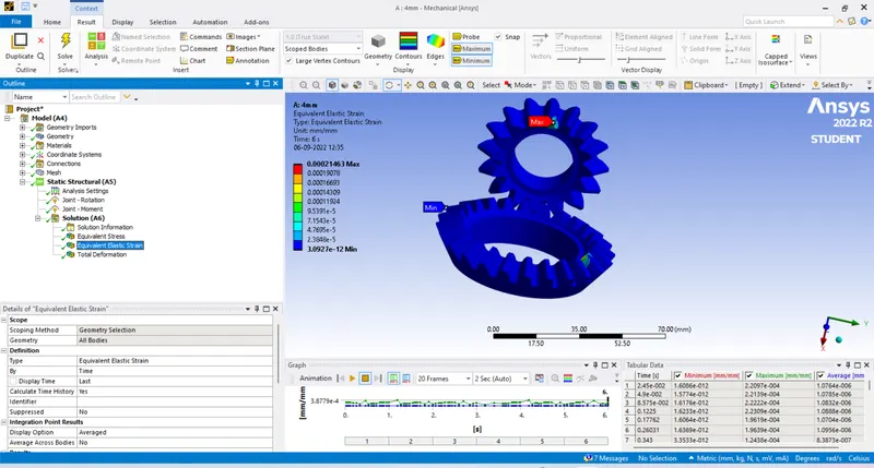
Total Deformation
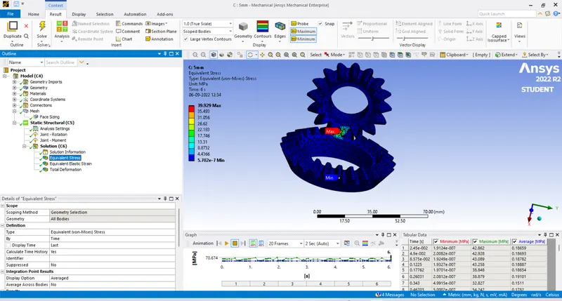
FOR 5MM
Von-Mises stress,
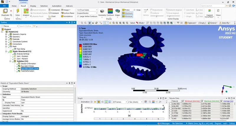
Equivalent elastic strain
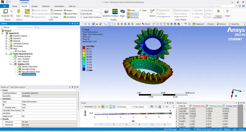
Total Deformation
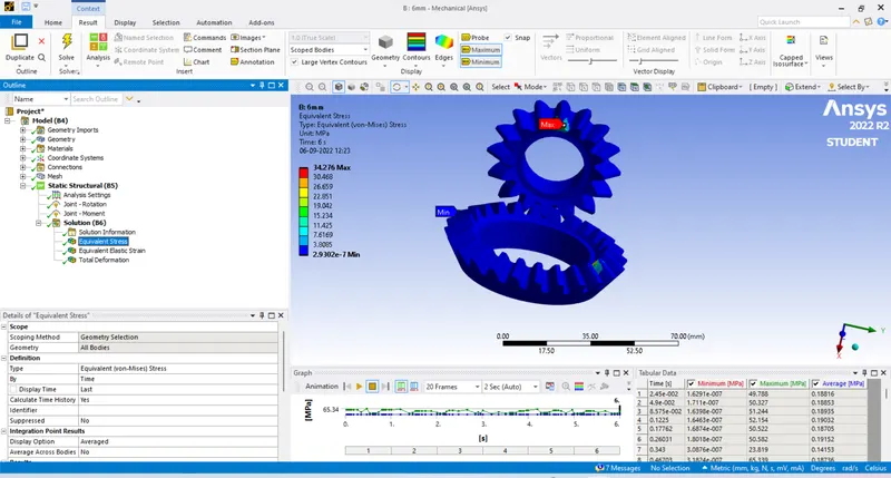
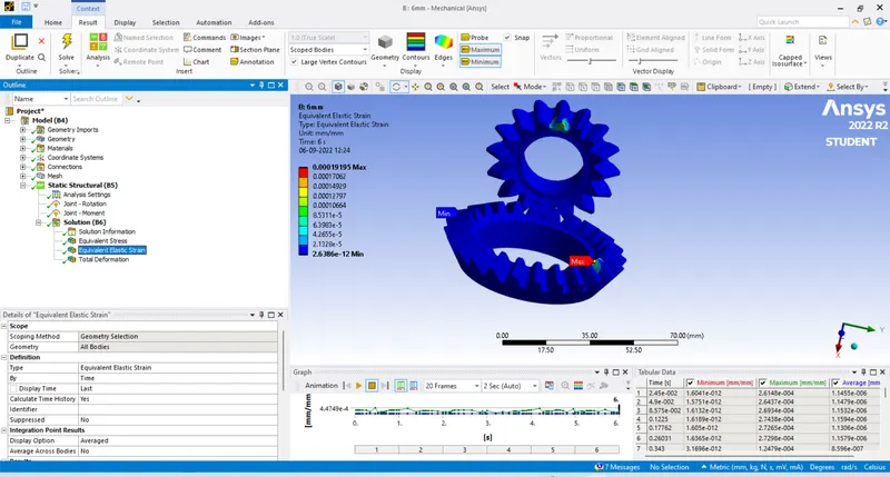
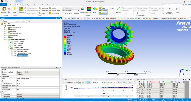
FOR 6MM
Von-Mises stress,
Equivalent elastic strain
Total Deformation
CONCLUSION:
| MESH ELEMENT SIZE | Von-Mises stress | Equivalent elastic strain | Total Deformation |
| 4MM | 40.06MPa | 0.00021463 | 64.5mm |
| 5MM | 39.929MPa | 0.00022393 | 64.5mm |
| 6MM | 34.276MPa | 0.00019195 | 64.5mm |
By looking at the analysed results we observe that:
- The Total deformation is same for all the three cases
- The Equivalent elastic strain is almost same when compared to all three cases.
- The Von-Mises stress are having bit variation when 4,5mm are compared with 6mm.
- So, to save time and get accurate results of the analysis 4mm can be prefered .
- But for highly accurate results and if you are prefering the Von-Mises stress element size of 6mm is suggested but remember computational time will be higher.