Week 2 Bevel Gear Challenge
Bevel Gear Challenge
OBJECTIVE:-
- Explain the process of the Grid Dependency test
- Setup a case of bevel gear simulation using given sets of input
- Perform a grid-dependent test for the bevel gear using different mesh element sizes of 6mm, 5mm, and 4mm.
- Provide inferences based on the results.
GRID DEPENDENCY TEST:-
We know that FEA is a numerical simulation approach. It is based on the approximation of results from adjacent elements and nodes. So more refined the mesh, the more accurate results. Ideally, the mesh size that tends to zero yields the perfect result but that is not practically possible. Hence we use different mesh sizes to achieve the best result possible. But we don't have any specific element size defined, that our results will be correct at the given mesh size. So usually the process of meshing starts with trial and error. We start with a coarse mesh and then proceed towards finer mesh. So when the variation in the result is minimal or almost identical, the simulation is said to have achieved grid independence. This means that the results of the simulation will remain the same even if we refine the mesh further. This whole process is called the Grid-Dependency test. For any simulation, at least 2 to 3 mesh sizes are checked before finalizing the results based on the grid dependency test. In finite element analysis the mesh creation is fundamental. Selection of mesh size is key parameter for the best result of the analysis. The grid dependency test is to find the optimum mesh size according to the result. Fineness of the mesh will improve the accuracy of the result. After some particular mesh size, further reduction of mesh size will not make improvements in the result, finding this particular point is the grid dependency test. While doing the grid dependency test the designer can be able to find the very near realistic figures of the results.
PROCEDURE:-
Start the simulation by opening with the Ansys workbench.
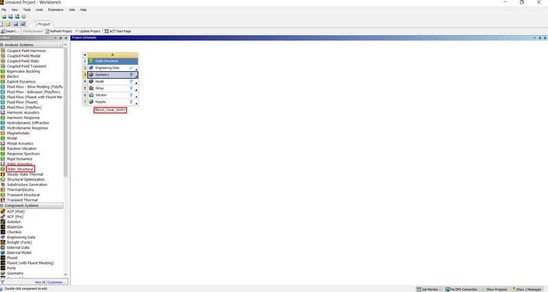
Select the static structure from the toolbox as shown below shown.
Defining Material:-
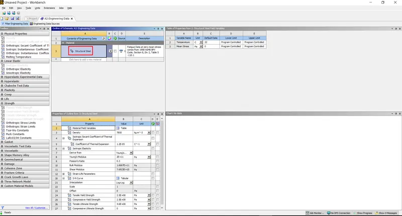
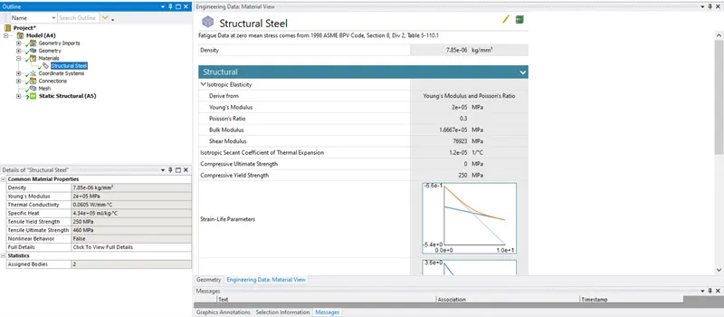
Update the engineering data as shown below. Select Structural Steel as the material.
Importing Geometry:-
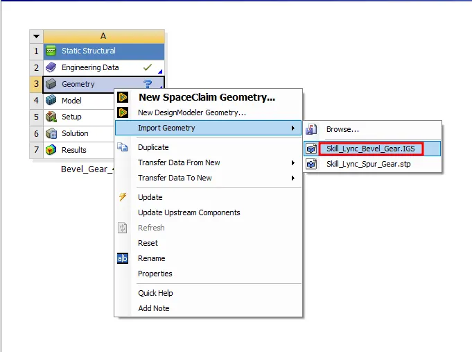
Also import the geometry from the browse with the updated geometry.
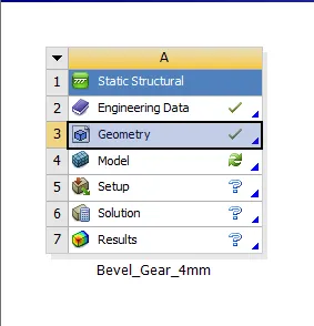
Now double click on Geometry to edit the model. Now select the surface of one gear and create a circle having it's center at the axis of rotation of the gear and then pull the created surface using surface to get the final geometry as shown. Repeat the same with the other gear.
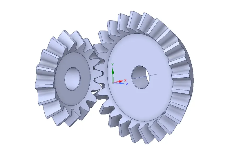
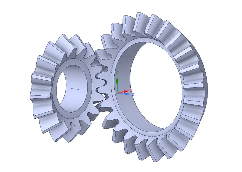
Now right click on Model and select Update to update the model, after that double click on the Model to open the model in ANSYS Mechanical interface.
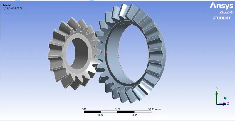
Rename and Unit System:-
Give the proper name for the shown gear as shown below.
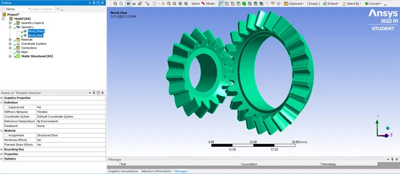
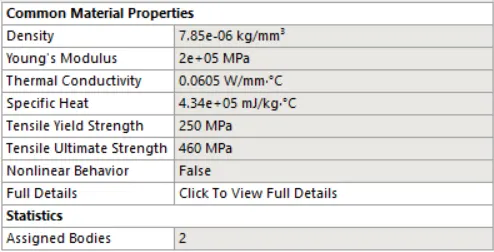
Use the material as the structural steel for both gears as shown below.
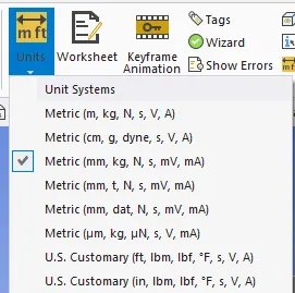
Select the proper unit systems for the given analysis results.
Creating Contacts:-
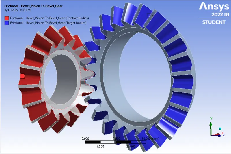
To create the contacts as the frictional, select all teeth faces w.r.t contact bodies and target bodies and click Apply as shown below and give parameter values.
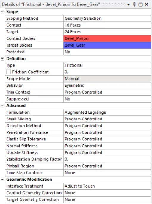
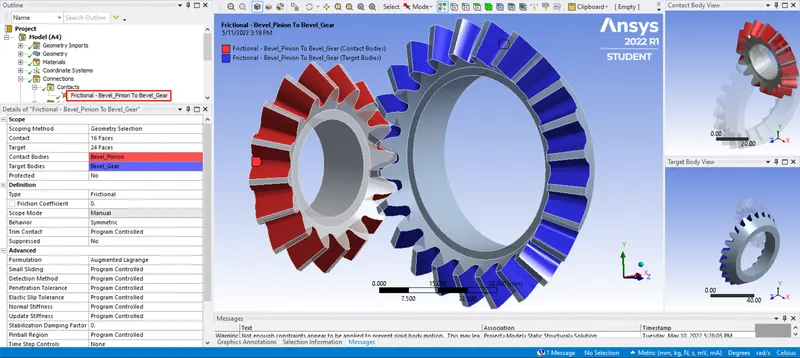
The below shows the selected gear teeth of contact bodies and target bodies.
Creating Joints:-
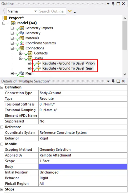
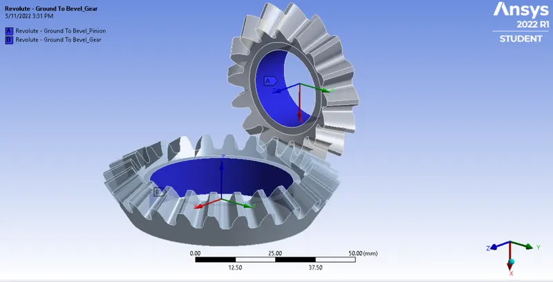
Create the connection for the 2 joints and give parameter values as shown in the image below.
Creating Mesh:-
Click on Mesh > Insert > Method. Now select the method as Tetrahedron and give other parameter values as shown.
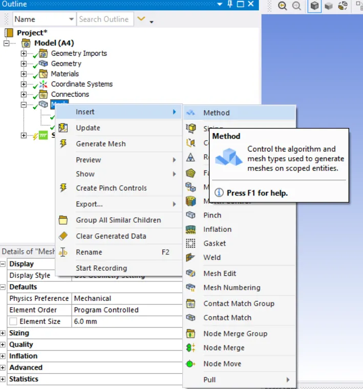
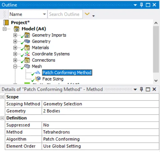
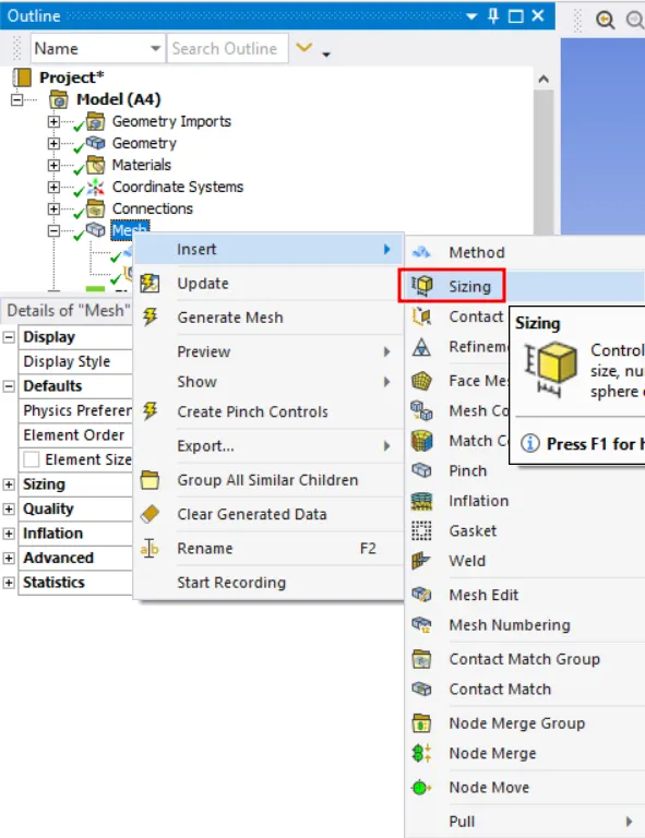
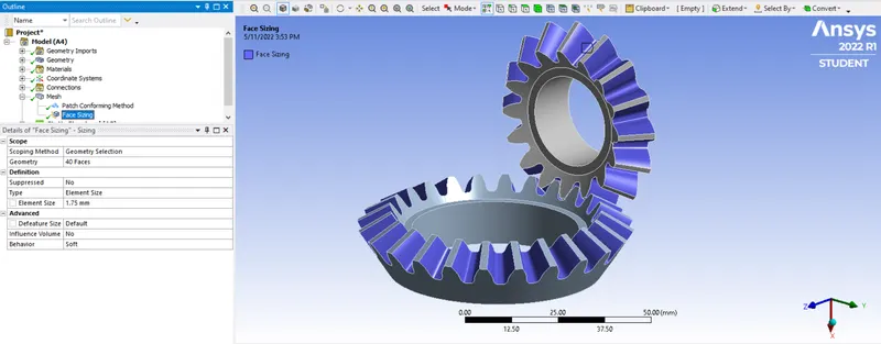
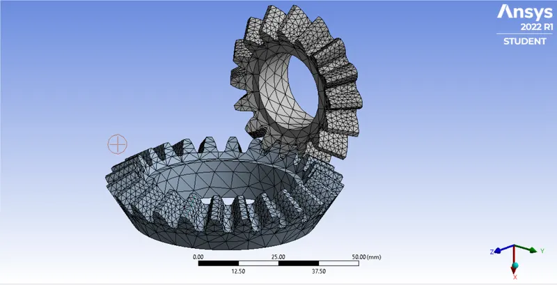
Now generate mesh with 6mm mesh element size but we see that the mesh is too coarse on teeth sections which will eventually lead to non converged solution. Here we can use Face Sizing, by which we can give a finer mesh size for teeth sections. Right click on Mesh and then Sizing, now select all the teeth faces and give mesh size as 1.75mm. Generate mesh now and we can see that the mesh size is moer finer on the teeth as compared to the gear faces shown in images.
Analysis Settings:-
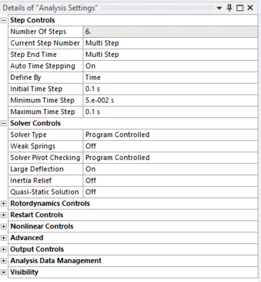
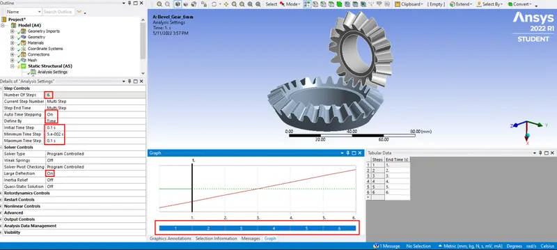
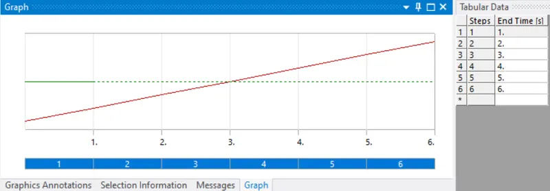
Define no. of steps as 6 and give other parameter values as shown in image.
Defining Joint Forces:-
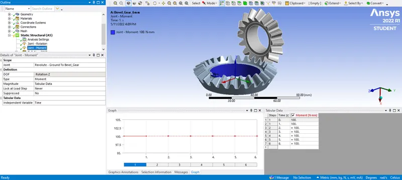
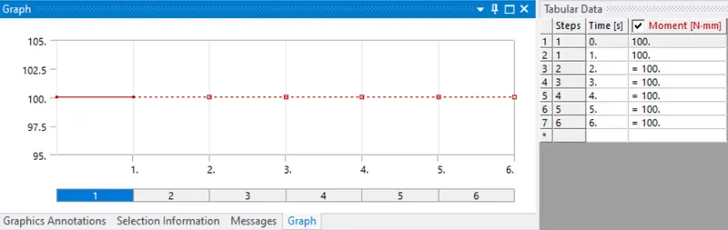
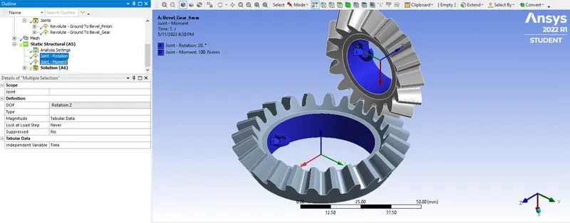
Joint Forces are given to both the gears as boundary condition. Moment of 100N-mm is given to the Bevel_Gear as shown.
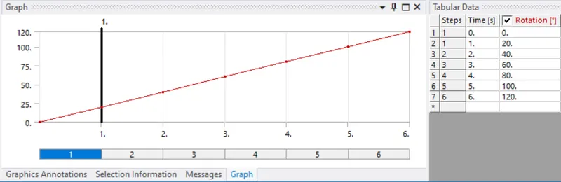
and Rotation of 120 degree is given to the Bevel_Pinion in 6steps.
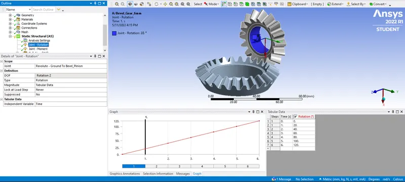
But the problem here is that the rotation of both the gears is in the same direction which is anticlockwise so we need to change the direction of rotation for Bevel_Pinion. Go to joints again and click on the concerned joint and then click on the Coordinate System. After that click on the Z-axis and then click on the axis opposite to this Z-axis, finally click on apply to change the direction of the Z-axis.
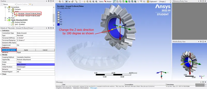
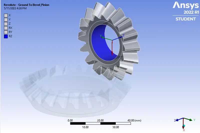
Now when we go to the joint force section again and click on the Joint-Rotation, we can see that the direction of rotation of Bevel_Pinion is reverced.
Requesting for Outputs:-
Go to Solution > Insert > Deformation > Total
Go to Solution > Insert > Strain > Equivalent
Go to Solution > Insert > Stress > Equivalent
Solving:-
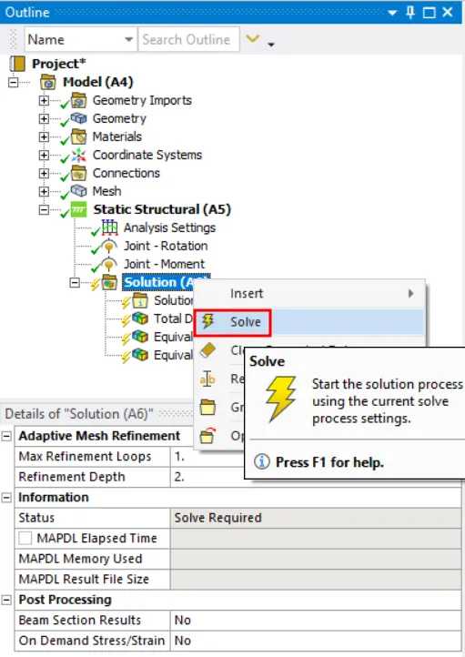
For getting solutions for Deformation, Strain and Stress right click on the Solution and then select the Solve option. This will take some time to solve.
NOTE:- Same Procedure can be used to simulate the process with 5mm and 4mm mesh element size.
RESULTS:-
6mm Mesh Size:-
Total Deformation -
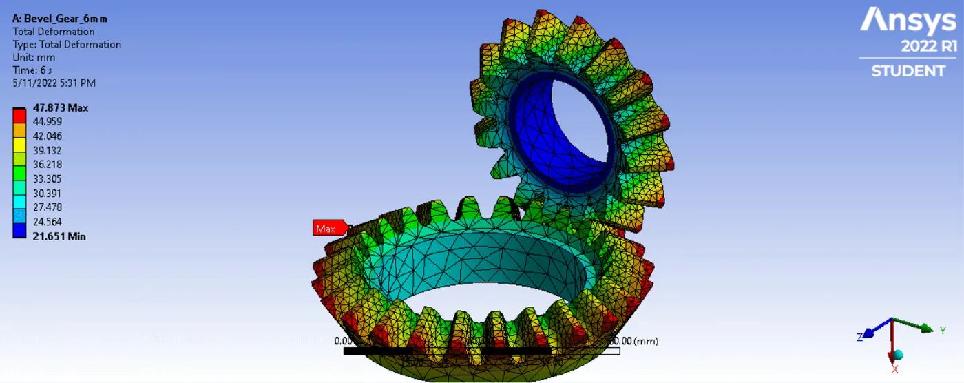
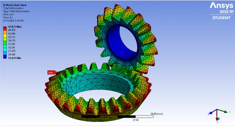
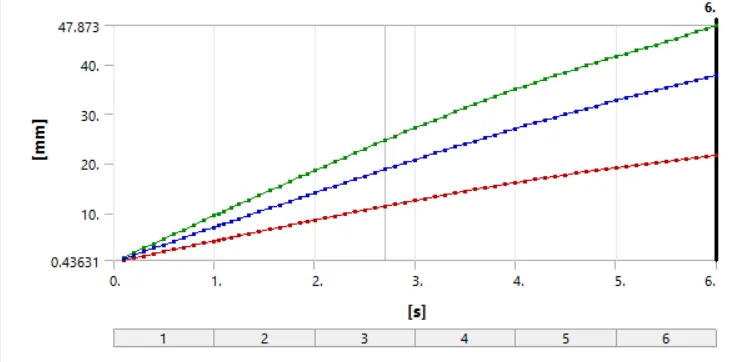
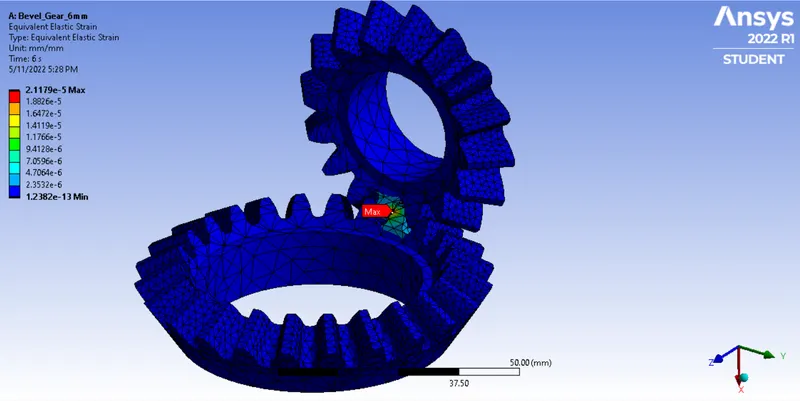
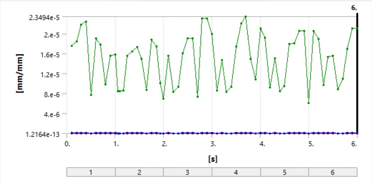
Equivalent Elastic Strain -
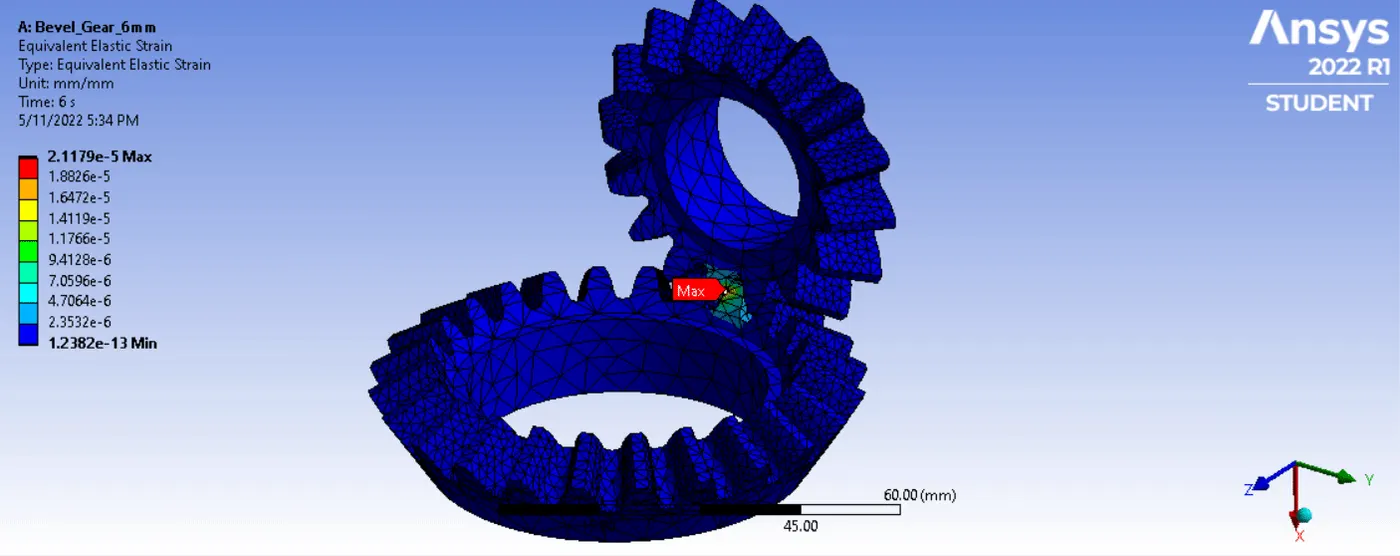
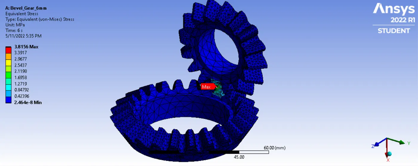
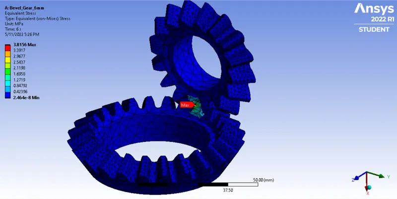
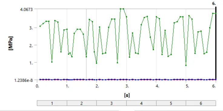
Equivalent Stress -
5mm Mesh Size:-
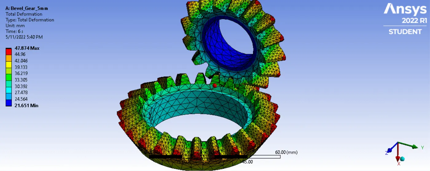
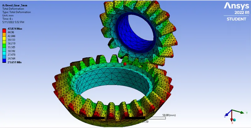
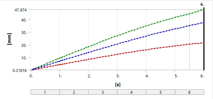
Total Deformation -
Equivalent Elastic Strain -
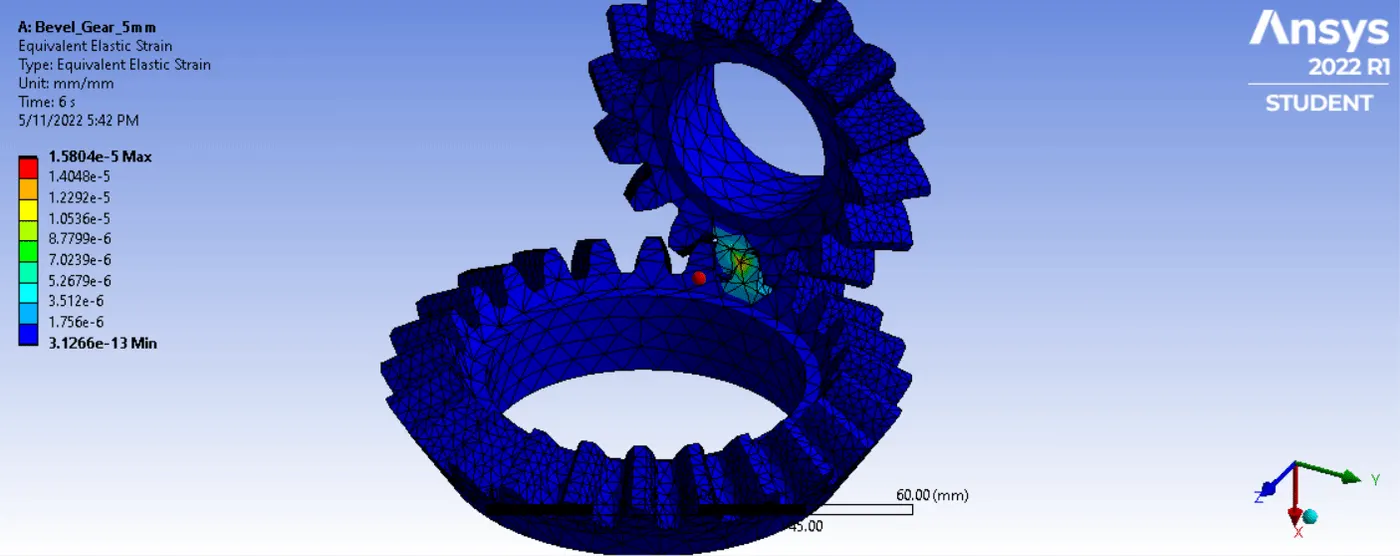
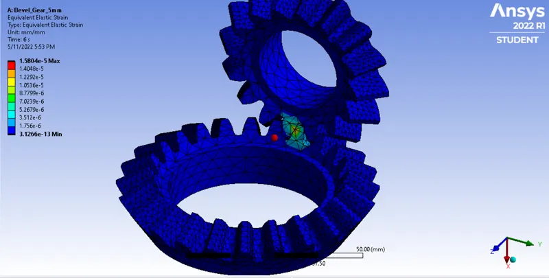
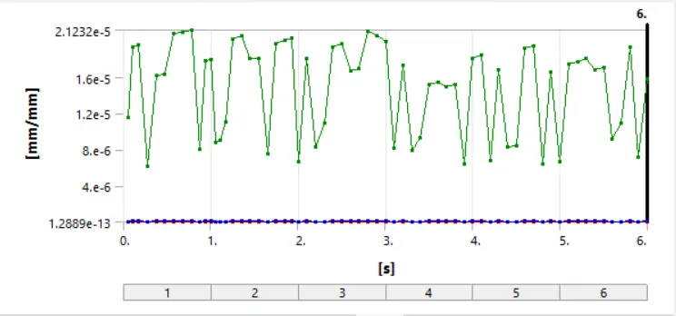
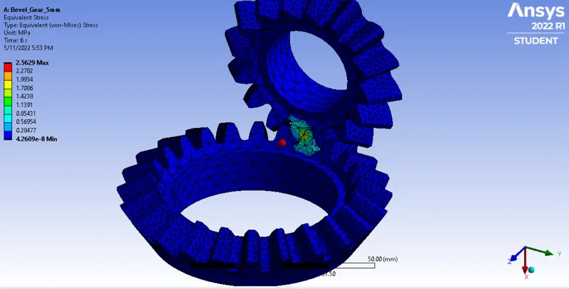
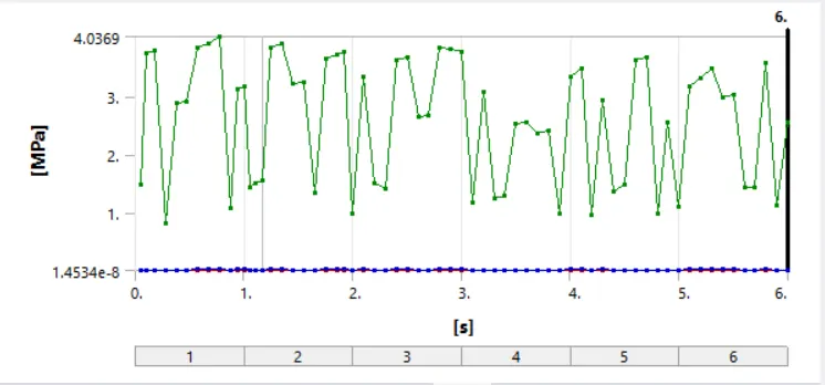
Equivalent Stress -
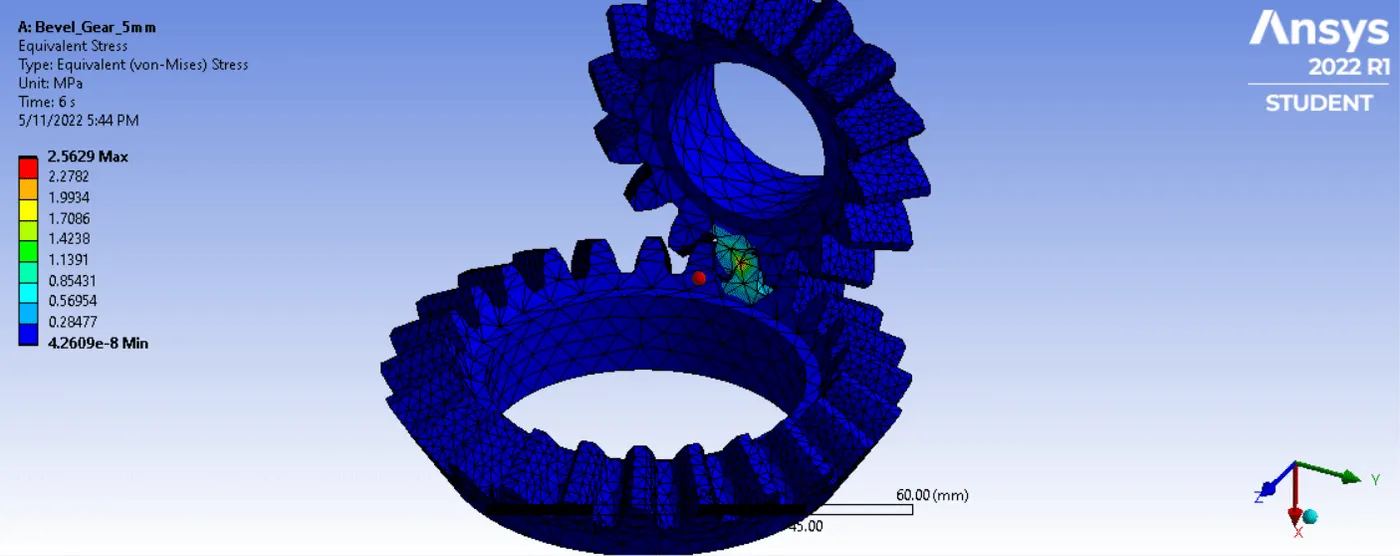
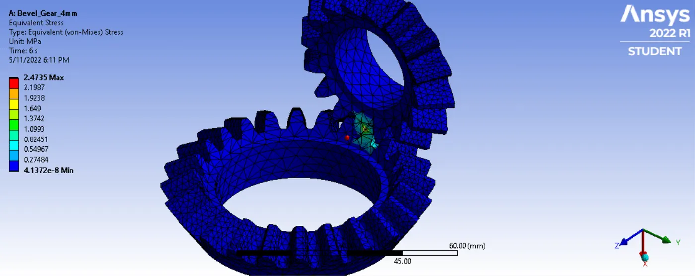
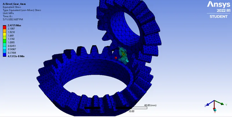
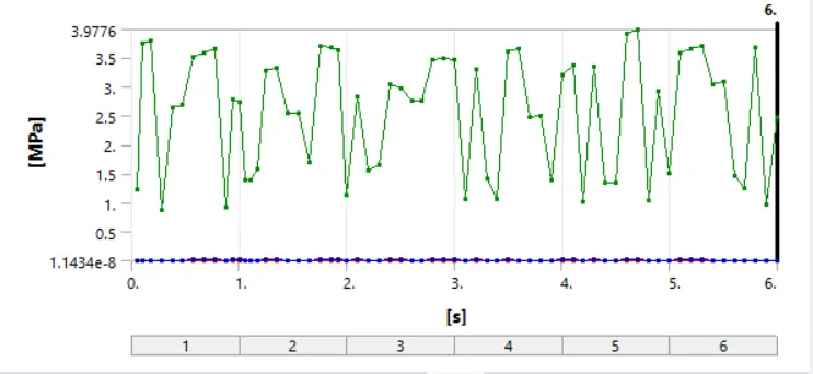
4mm Mesh Size:-
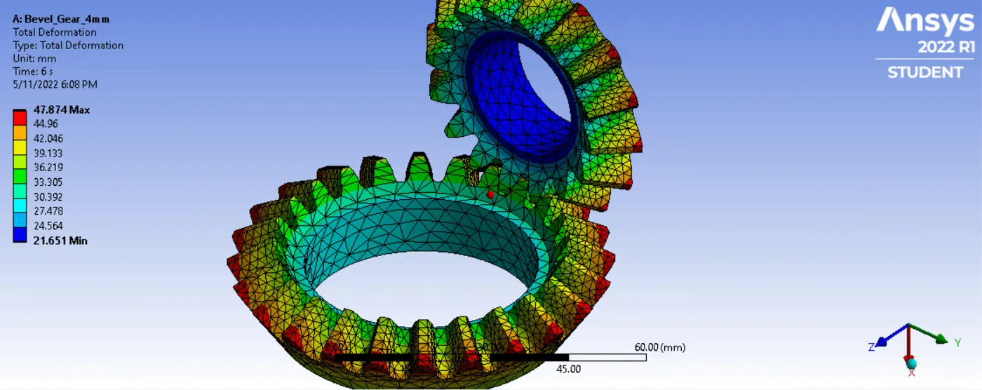
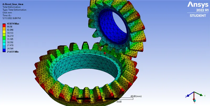
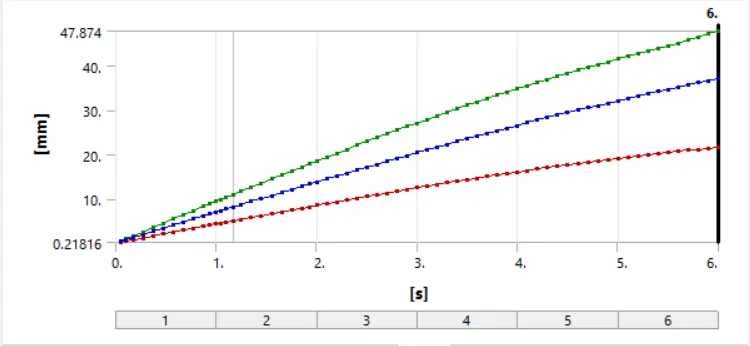
Total Deformation -
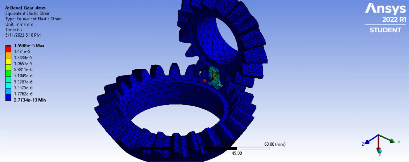
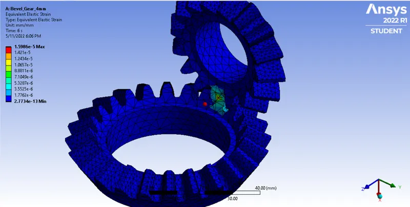
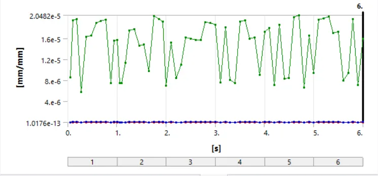
Equivalent Elastic Strain -
Equivalent Stress -
COMPARISION:-
| 4mm Mesh Size | ||
| Max. | Min. | |
| Total Deformation | 47.874mm | 21.651mm |
| Eq. Elastic Strain | 1.5986*10^-5 | 2.7734*10^-13 |
| Eq. Stress | 2.4735Mpa | 4.1372*10^-8Mpa |
Time - 16m 23s
| 5mm Mesh Size | ||
| Max. | Min. | |
| Total Deformation | 47.874mm | 21.651mm |
| Eq. Elastic Strain | 1.5804*10^-5 | 3.1266*10^-13 |
| Eq. Stress | 2.5629Mpa | 4.2609*10^-8Mpa |
Time - 13m 39s
| 6mm Mesh Size | ||
| Max. | Min. | |
| Total Deformation | 47.874mm | 21.651mm |
| Eq. Elastic Strain | 2.1179*10^-5 | 1.2382*10^-13 |
| Eq. Stress | 3.8156Mpa | 2.464*10^-8Mpa |
Time - 11m 39s
CONCLUSION:-
We can clearly see in the tables mentioned above that when we switch from 6mm mesh size to 5mm mesh size, there is significant chance in the values of Eq. Stress and Eq. Elastic Strain but again when we switch from 5mm mesh size to 4mm mesh size, there is no significant chance in the values of Eq. Stress and Eq. Elastic Strain. Which means the accuracy of solution achieved with 5mm and 4mm mesh size is almost the same but when we observe the time taken for simulation results outputs in both the cases, we find that the time taken is more in the case of 4mm mesh size with almost same solution accuracy as that of the 5mm mesh size, that is why 5mm mesh size is the most suitable one for this simulation.