Week 2 Bevel Gear Challenge
Grid dependency test To get the optimum results we will go the course mesh to the finer mesh by decreasing the elmental size and the gird dependency test means the value what we want should not change even we decrease the elemental size(it should be same i.e independent of the messh size) for example if we have equivalent stress of 4Mpa at elemnt size 0f 6mm but we want to optimum value hence we decrease the elment size to 5mm now we gat equivalent stress has 5.43Mpa and when we decraese further elemnt size to 3mm we gat value as 5.47 Mpa after furether reduing the elemnt size the value does not change only the computional time increses but no increases in the value hence we can say the solution is grid independcy has reached .
Producer-
1. First we chosse static structural from Ansys GUI.
2. We add material from the enginnering data and poroperties of the material such as yield strength,youngs modulus,shaer modulus,yield ultimate strength and bulk modulus.
3.We import the geometryb to the space claim.
4. we rename the the model as big gear and the small gear and we add material to the respective gears. after adding tha meterial we make coonections bewteen the gears by selecting the tooths of the gears and we give the contact between geras as frictionless and in geometry modification we give adhust to touch. we have to provide joints to the respective gears i.e revoltary joint for the both gears. and we make sure taht bothe gars should rotate in z direction.
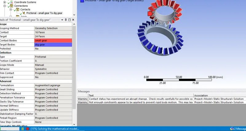
Fig1- Providing the cotact details between the gears
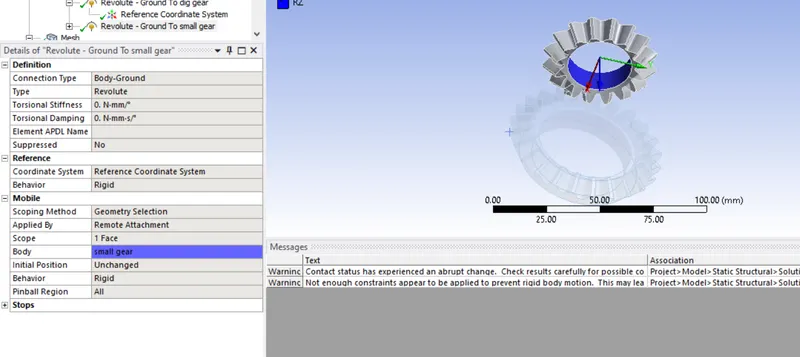
Fig2- Providing the joint For the small gear
5. We will mesh the gear of the global elment size 6mm and we give sizng of elemnt size of 1.75 mm bewteen the teeth of the since thay will come in to contact and we will take reult betwwen the teeths.
6.In anlysise setting we give number of steps as 6 meaning the rotation given to gears are divided in to six times (i,e 120 rotation is divided in to six rotation ) and we use intial time step as 0.1 sec and minimum time step as0.0005 sec and maximumu time interval as 0.5 sec .
7.We give joint load to the joints i,e rotation for for small gear and moment for another big gear becuse to calculate the equivalent strain and from that we calculate equivalent stress.we give moment of 100Nm. and small gear should rotate in clockwise and big gear shoiuld rotate in the anticlockwise direction to obtain proper motion betwwen gears.
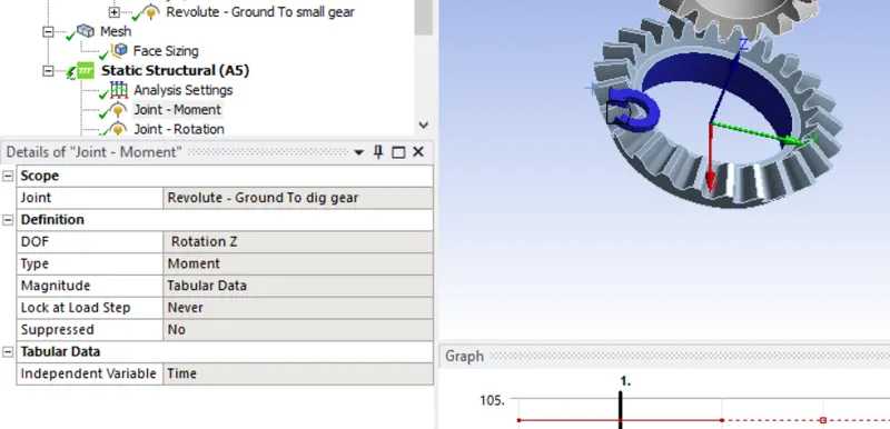
Fig3-providing the joint lad for the big gear( moment in the clock wise direction)
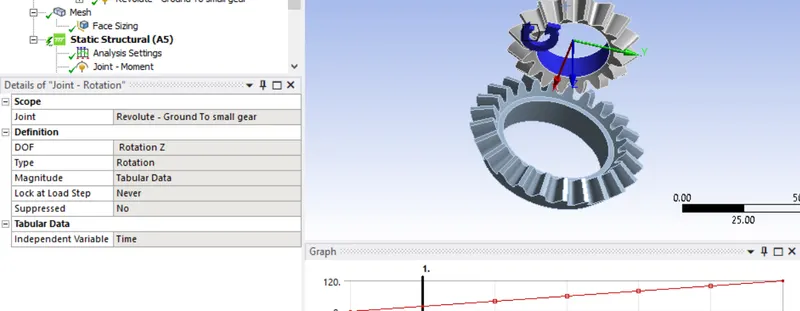
Fig4- Providing the joint lad for small gear(Rotation in the anticlockwise direction)
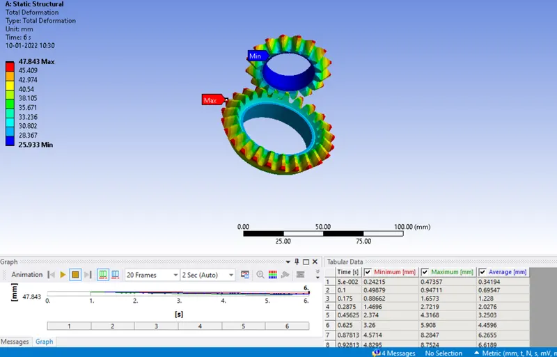
Fig 5- Total deformation For 6mm
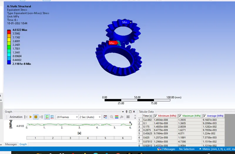
Fig 6- Equivalent stress for the 6mm
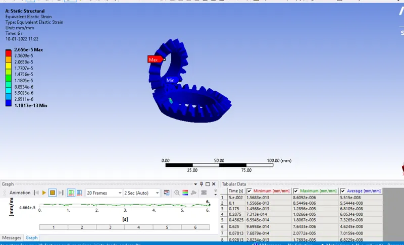
Fig7-Eyuivalent strain for 6mm
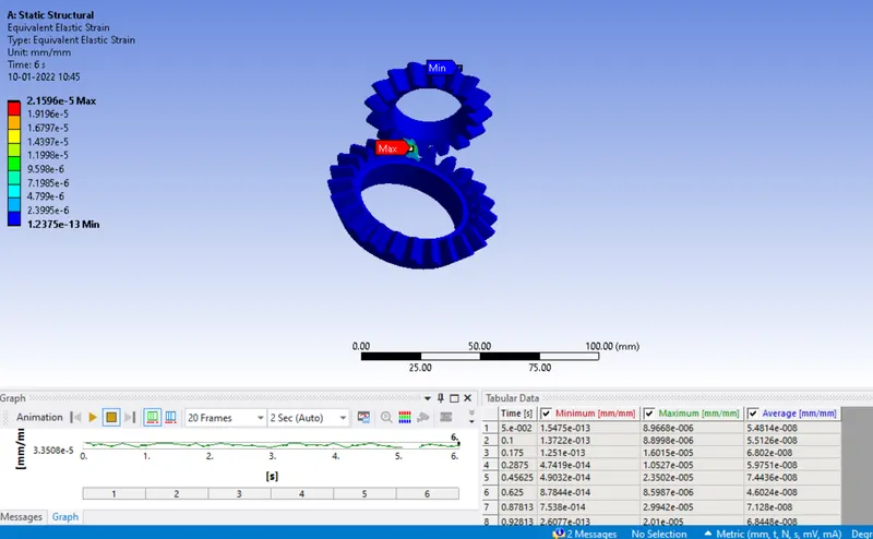
Fig8-Equivalent strain For 5mm bending
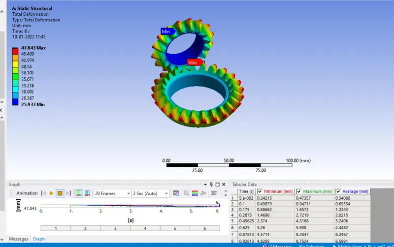
Total deformation For 5mm
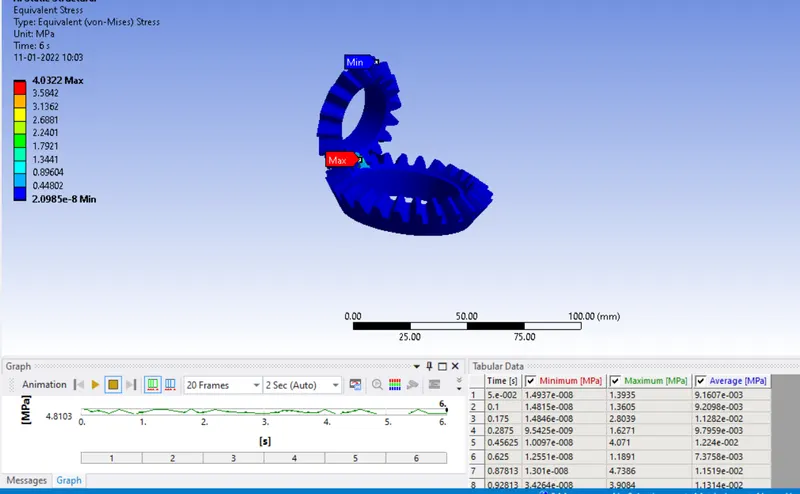
Fig-Equivalent stress for5mm
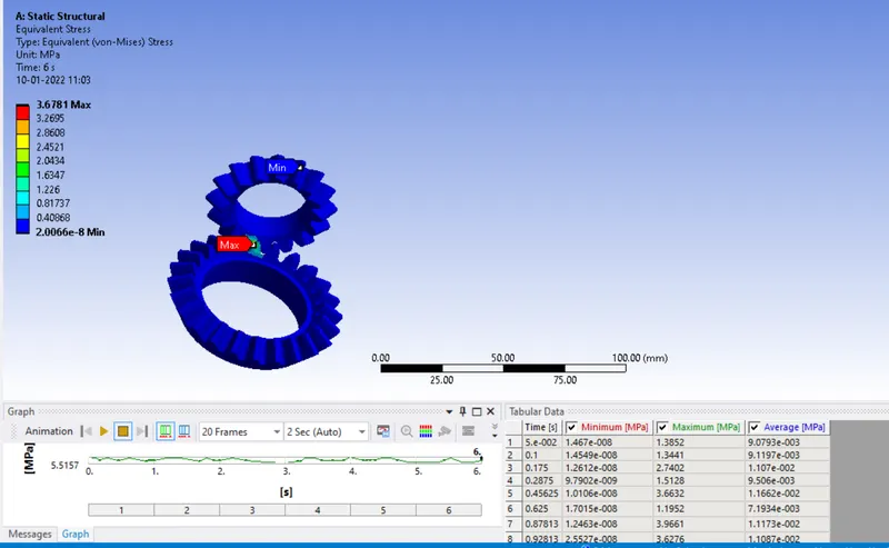
Fig8-Euqivalent stress for the 4mm
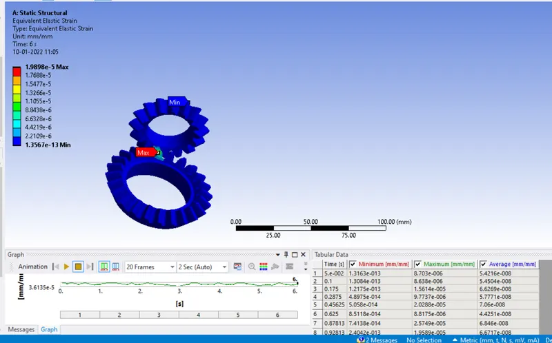
Fig9-Equivalent strain for 4mm
| Mesh size | Equivalent stress(Mpa) | Total Deformation |
| 6mm | 4.032 | 47.83 |
| 5mm | 4.8103 | 47.83 |
| 4mm | 5.517 | 47.83 |
FRom above table we can see that the equivalent stress goes on increasing as the mesh size decreases beacuse as the more number of the elements and total deformation for all threee mesh size remains same which proves Drid depedent test.