Week 2 Bevel Gear Challenge
Aim
a) To perform grid dependency test for a bevel gear simulation for the given mesh sizes
b) Analyse the given bevel gear system in terms of Von-Mises stress, Equivalent ealstic strain and Total Deformation
1. Introduction
Grid dependency test is generally used to observe the effect of mesh element size on the output parameters. Mesh element size is a governing factor whether our result will converge with the given criteria for one or more points. Element size in the direction of finer mesh always give better results as compared to the coraser one. In this test first we give a predefined element size value to the setup and then after we will decrease the element size in steps. When the output parameters will not be affected from a particular mesh size then this will be a critical value below which the solution is acceptable.
2. Procedure
2.1 First we have opened ANSYS WB and then we selected the static structural analysis tool from toolbar.
2.2 Material
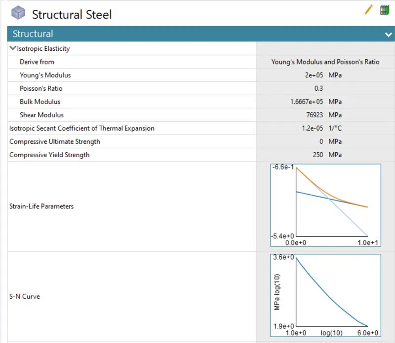
By clicking on the engineering data, we selected the structural steel as working material. The properties of structural steel are given below:
2.3 Editing Geometry in Spaceclaim
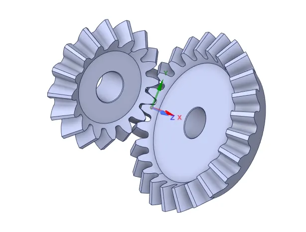
After selecting the material, geometry was inserted by clicking on import geometry option. Bevel gear geometry was then opened in space claim and edited for the convinience of the solution as given below:
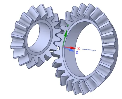
For both the bevel gears, a round middle portion was eliminated upto a suitable radius as given below:
2.4 Connections
2.4.1 Contact Details
First the bevel gears were renamed as small and large gear as per the given size. After renaming the contact was defined as given below by selecting the contact faces manually:
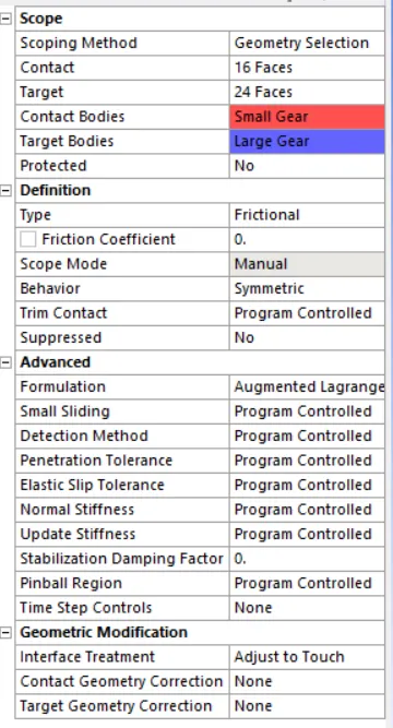
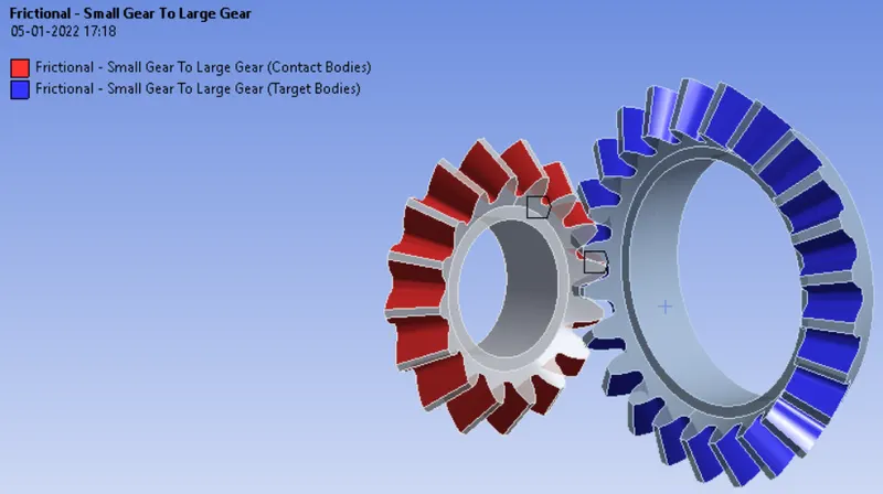
As seen above there are total 40 faces were in contact and behaviour of contact was symmetric. Formulation was selected to Augmented Lagrangian to avoid the noise, chattering and vibration effect.
2.4.2 Joints
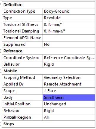
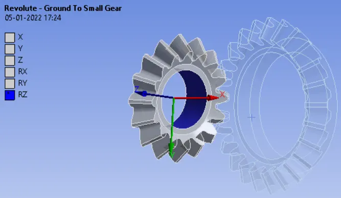
small gear -
large gear -

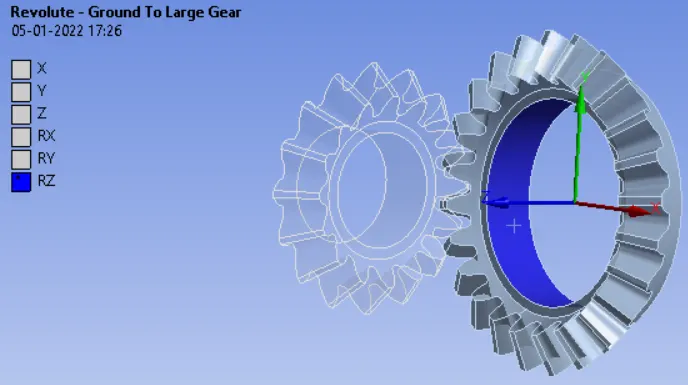
As seen above, for both the gears ground to body joints were created. Inner faces of two gears are in contact with the ground.
2.5 Mesh
As in the bevel gear, the surface of contact should be of finer size so we have generated a finer size mesh for contact surfaces by selecting the face sizing option from the mesh tool. Mesh sizes given for bevel gears are 4, 5 and 6. Schematic diagram of meshed gears are given below:
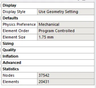
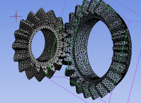
For the above illustration we have used the 1.75 mm as mesh size. We will use the mesh size of 4, 5 and 6 later for parameteric study.
2.6 Analysis Settings
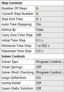
As seen above, complete motion of gears was divided into six steps. Aoto time stepping was on and definition of steps was done by time. Initial time step was 0.1s, maximum time step 0.5s and the minimum time step was .01.
2.7 Joint Loads
2.7.1 Rotation
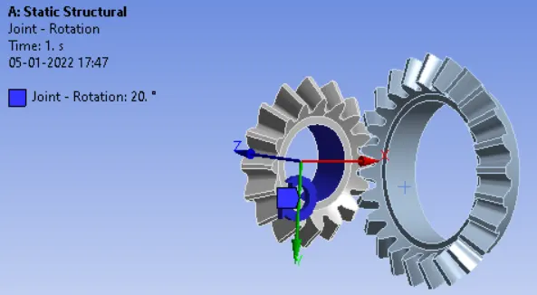

As seen above, small bevel gear was given a rotation about Z axis in six steps. The total rotation was 120 degree.
2.7.2 Moment
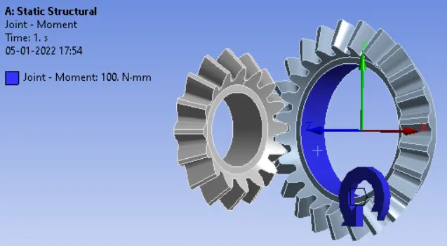

As seen in above figure, moment of magnitude 100 N-mm was given to the large gear in six steps.
2.8 Results
After solving the above setup, resuts were extracted in the form of Equivalent Stress, Total Deformation and Equivalent Elastic Strain as given below:
Equivalent Stress - 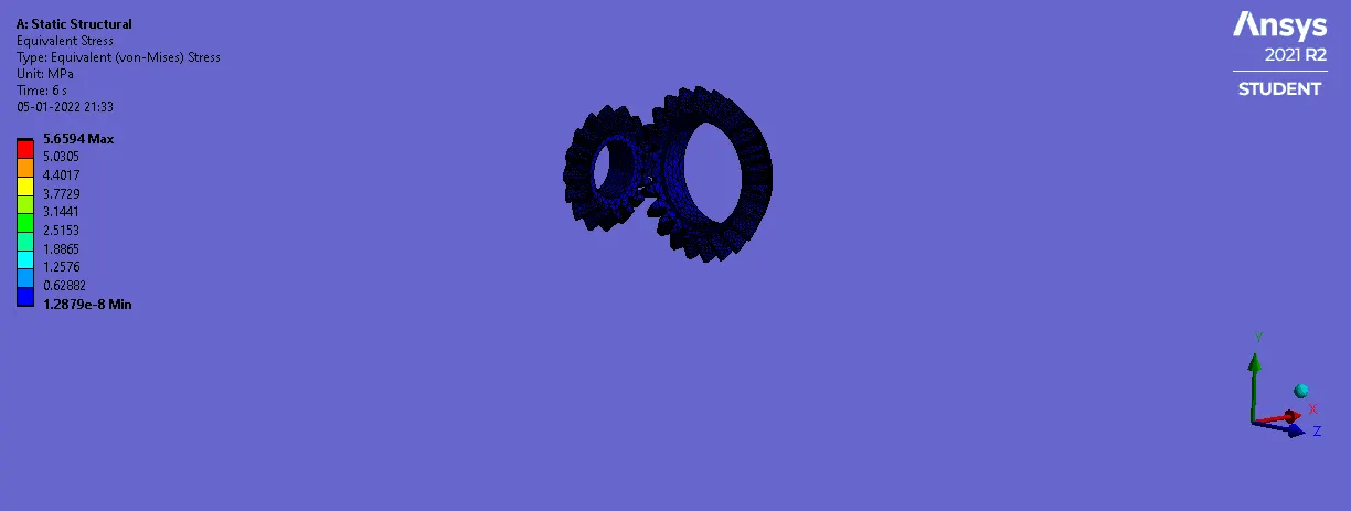
Total Deformation - 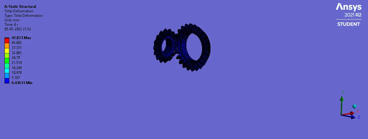
Elastic Strain - 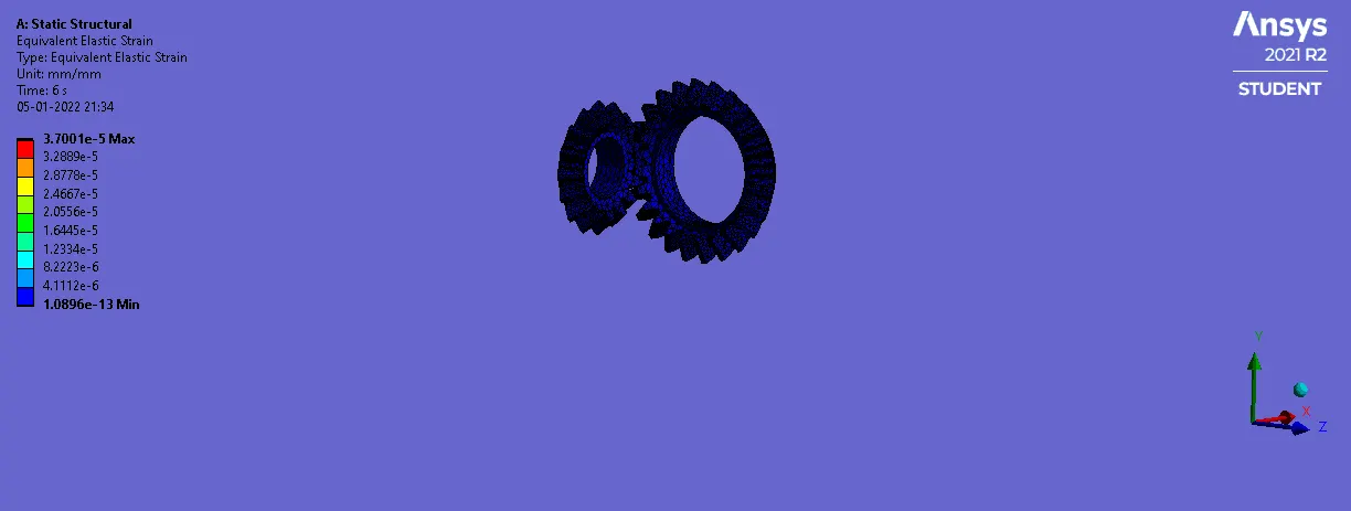
3. Parameteric Study
Creating the mesh size as input parameter, We have used three design points for 4, 5 and 6 mm of element size. The corresponding results of output parameters are given below:
a) Equivalent Stress:
|
Mesh Size (mm) |
Maximum Stress (MPa) |
Minimum Stress (MPa) |
Average Stress (MPa) |
|
4 |
5.6594 |
2.54e-8 |
0.012083 |
|
5 |
4.0258 |
1.6271e-8 |
0.012281 |
|
6 |
3.6386 |
2.7885e-8 |
0.012381 |
b) Total Deformation
|
Mesh Size (mm) |
Maximum Total Deformation (mm) |
Minimum Total Deformation (mm) |
Average Total Deformation (mm) |
|
4 |
47.873 |
21.651 |
37.135 |
|
5 |
47.873 |
21.651 |
37.511 |
|
6 |
47.873 |
21.651 |
37.677 |
c) Equivalent Elastic Strain
|
Mesh Size (mm) |
Maximum Elastic Strain (mm/mm) |
Minimum Elastic Strain (mm/mm) |
Average Elastic Strain (mm/mm) |
|
4 |
3.70005025615683E-05 |
1.2951841205435E-13 |
7.41001572186973E-08 |
|
5 |
2.75950314971851E-05 |
1.7280162258198E-13 |
7.4950824928867782E-08 |
|
6 |
2.03569656150648E-05 |
1.3942446914876E-13 |
7.58182517515325E-08 |
4. Conclusions
a) Grid dependency test was successfully done with given mesh element size values.
b) Given bevel gear was successfully simulated with ANSYS Workbench.
c) It was clear from the design points that finer then mesh size, more will be the accuracy. We can easily get the convergence conditions with the small step time size.