Week-6 Challenge: EV Drivetrain
1) Types of power converter circuits are employed in electric and hybrid electric vehicle
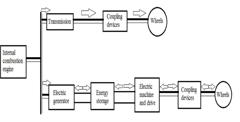
A hybrid-electric vehicle has two source of power one by an electric motor and the other source of motive power can come from a number of different technologies, but is typically provided by an internal combustion engine designed to run on either gasoline or diesel fuel.
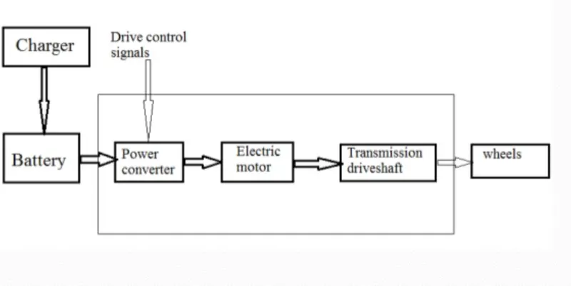
In case of a pure EV it has only battery as the power source
A typical Drivetrain of EV is as shown below
A typical Drivetrain of HEV is as shown below
Now for the part of Electric power or source, certain types of converters are employed in an EV or HEV.
For the control of electric power supplied to the load for power conditioning the conversion of electric power from one form to other is necessary.
The different types of power converters are
- AC to DC converters
- AC to AC converters
- DC to DC converters (DC choppers).
- DC to AC converters (Inverters).
- AC TO DC Converters (Rectifiers) –
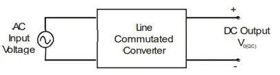
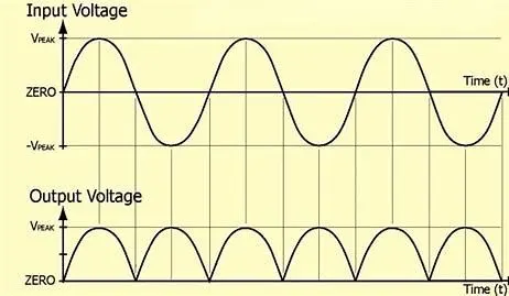
These are AC to DC converters. The line commutated converters are AC to DC power converters. These are also referred to as controlled rectifiers. The line commutated converters (controlled rectifiers) are used to convert a fixed voltage, fixed frequency AC power supply to obtain a variable DC output voltage.
Applications of Ac To Dc Converters
- Speed control of DC motor in DC drives.
- HVDC transmission.
- Battery Chargers.
2 . AC TO AC Converters –
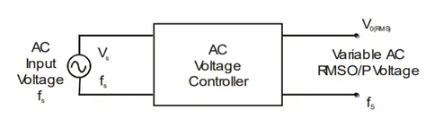
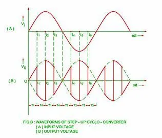
The AC voltage controllers convert the constant frequency, fixed voltage AC supply into variable AC voltage at the same frequency using line commutation.
AC regulators are mainly used for
- Speed control of AC motor.
- Speed control of fans (domestic and industrial fans). AC pumps.
- DC to DC converters (DC choppers)
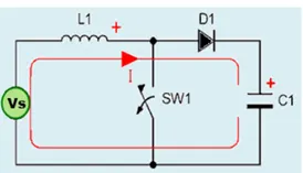
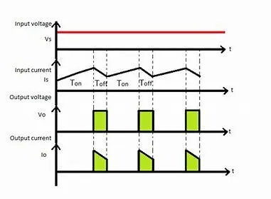
A DC-to-DC converter is a device that accepts a DC input voltage and produces a DC output voltage. Typically, the output produced is at a different voltage level than the input. In addition, DC-to-DC converters are used to provide noise isolation, power bus regulation, etc.
Many DC operated applications need different levels of DC voltage from a fixed DC source.Some of these applications include
- Subway cars,
- DC traction systems,
- Control of large DC motors,
- Battery operated vehicles, trolley buses, etc.
4) DC to AC converters (Inverters).
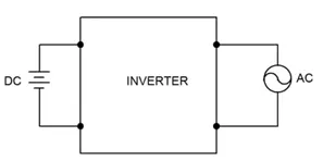
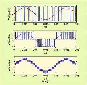
DC to AC converters is mainly designed for changing a DC power supply to an AC power supply. The common inverter technology used in electronics is to convert a voltage source from a battery into an AC signal. Generally, they operate with 12 volts and commonly used in applications like automotive, lead-acid technology, photovoltaic cells, etc.
Inverters are widely used in
- Standby power supplies,
- UPS,
- Induction heating,
- Induction motor drives etc
USAGE OF CONVERTERS IN EV AND HEV DEPENDS ON TYPE OF VEHICLE
1) Rectifier may be used at the charging point when plug in HEV are charged via grid supply which is in AC to store the charge in Battery which is in DC
2) Choppers may be used with in car for supplying low voltage to accessory or sensors of the vehicle
3)Inverter may be used in the vehicle ifm the EV or HEV are used as part of Smart grid where the car battery can provide power to home appliances.
--------------------------------------------------------------------------------------
2) Given
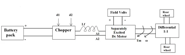
72V battery pack
Rated Armature voltage= 72 V
Rated armature current= 400 A
Ra= 0.5Ω, KΦ= 0.7 Volt second
Chopper Switching frequency= 400 Hz
w = (V/k*phi) - (Ra/(k*phi)^2)*T
According to the requirement
we need to find the value of speed at steady state with duty ratio of 70%
At the end of DC motor the voltage availble after 70% duty ratio from battery pack
Va = D*Vbatterypack
Va = 0.7*72 = 50.4V
so substituting this vslue of v in the w equation we have
w = (50.4/0.7)-(0.5/(0.7)^2)*T
on solving we have
T = 70.58 - 0.98w
Now we have a given eqaution at steady state as
T = 24.7 + 0.00051w^2
as at steady state these two values of torque would be same therefore
70.58 - 0.98w = 24.7 + 0.00051w^2
On solving
.0051w^2 + 0.98w - 45.88 = 0
on solving we have two values of w
38.92 , -238.3
as we need to take positive value of speed as vehicle is moving in forward direction
w at steady state is 38.92 rad/sec
3)
to implement the equation
w = (V/k*phi) - (Ra/(k*phi)^2)*T
Step 1
Constant block used for V , Ra and kphi
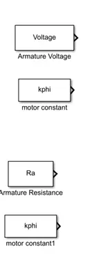
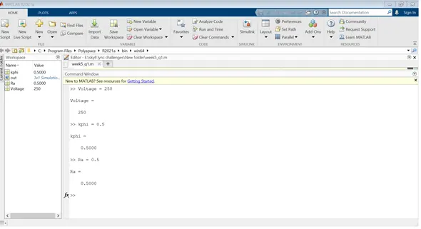
and the constant are treated as variable whose value is updated from base workspace
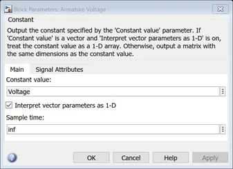
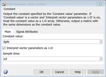
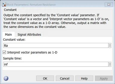
And these value are updated from command window
Step 2)
The value of torque is provided as a variable value by using a slider gain , constant . The variation of this variable is shown via custom guage
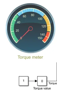
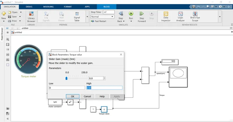
The value of torque is given in the range from 0 to 150 Nm
Simulation run time is given as inf so that the slider can be changed
Step 3)
The values of (V/k*phi) is passed via a divider to implement the equation and in a similar manner this equation (Ra/(k*phi)^2)*T is also implemented
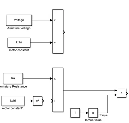
STEP 4) After that they are passed via adder and then to XY GRAPH AND DISPLAY TO GET THE RESULT
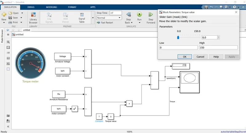
THE PLOT OBTAINED AFTER THE SIMULATION IS INLINE WITH THE THEORITICAL PLOT
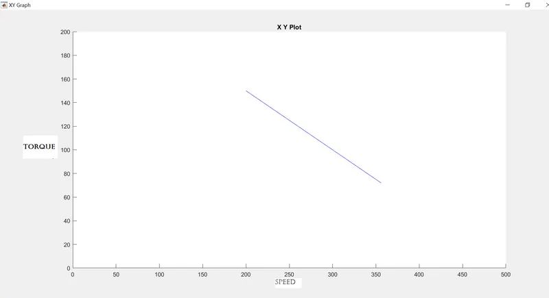
THE EQUATION IS IMPLEMENTED
---------------------------------------------------------------------------------------------------------
4) As per the author, he has tried to put a light on comparison of both motors. Its tabulated and shown as below.
|
Sl.No. |
Parameter |
BLDC motor |
AC Induction Motor |
|
1 |
Rotor |
Rotor includes two or more permanent magnets that generate a DC magnetic field |
The induction rotor has no magnets – just stacked steel laminations with buried peripheral conductors that form a “shorted structure.” |
|
2 |
Stator |
Identical to AC induction motor. Both have three sets of “distributed windings” that are inserted within the stator core. |
Identical to BLDC motor. Both have three sets of “distributed windings” that are inserted within the stator core. |
|
3 |
Starting torque |
A brushless DC motor produces no starting torque when directly connected to fixed frequency utility power. |
When a 3-phase induction motor is connected to utility type 3-phase power, torque is produced at the outset; the motor has the ability to start under load. |
|
4 |
Compatibility with utility power |
They really need the aid of an inverter whose “phase” is maintained in step with the angular position of the rotor. |
Induction motors are directly compatible with conventional utility power. No inverter is needed. |
|
5 |
Operating Supply |
They can operate on DC supply. |
They cannot operate from DC; AC is a must. |
|
6 |
Shaft speed |
Shaft speed is not proportional to line frequency. |
Shaft speed is proportionate to line frequency. Hence, when used with utility power, they are constant speed machines. |
|
7 |
Digital control |
DC brushless drives require an absolute position sensor. |
Induction drives require only a speed sensor. |
|
8 |
Rotor heat & cooling |
Less rotor heat is generated with the DC brushless drive. Rotor cooling is easier and peak point efficiency is generally higher for this drive. |
More rotor heat is generated and hence its cooling is difficult. |
|
9 |
Power factor |
DC brushless drive can also operate at unity power factor. |
The best power factor for the induction drive is about 85 percent. |
|
10 |
Strength of magnetic field (B) & efficiency |
No easy way of changing B with permanent magnets & hence efficiency is optimized. |
Induction machines have no magnets and B fields are “adjustable,” since B is proportionate to V/f (voltage to frequency) and hence efficiency is maximized. |
|
11 |
Higher machine size |
With DC brushless, as machine size grows, the magnetic losses increase proportionately and part load efficiency drops. |
With induction, as machine size grows, losses do not necessarily grow. |
|
12 |
Maintenance & Cost |
Permanent magnets are expensive. Rotors are also difficult to handle due to very large forces that come into play when anything ferromagnetic gets close to them. |
Induction motors retain a cost advantage over BLDC machines. Also, due to the field weakening capabilities of induction machines, inverter ratings and costs appear to be lower, especially for high performance drives. Since spinning induction machines produce little or no voltage when de-excited, they are easier to protect. |
|
13 |
Control |
Comparatively easier to control. |
Induction machines are more difficult to control. The control laws are more complex and difficult to understand. Achieving stability over the entire torque-speed range and over temperature is more difficult with induction. |