Week -2
Aim :
To
1. Make a Simulink model of Doorbell using solenoid block, where when the switch is closed the electromagnet receives electrical power from the battery and pulls the metal arm to hit the bell producing sound. Create a situation where the switch is closed for 2 seconds and then released. Observe the physical movement of the plunger.
2. Use a thermistor to sense the temperature of a heater & turn on or turn off the fan as per below conditions. Temperature source: 20 °C from 0 to 10 seconds, 27 °C from 10 to 30 seconds, 23 °C from 30 to 50 seconds
Fan conditions: ON if the temperature above 25 °C, OFF otherwise
Simulink Modelling :
1. Door Bell using solenoid block:
The circuit diagram for the door bell is given below,
As can be seen from the circuit diagram, the components required to form the circuit are:
1. Battery
2. Switch
3. Metal arm and bell
4. Solenoid
Given below is the simscape model for a doorbell,
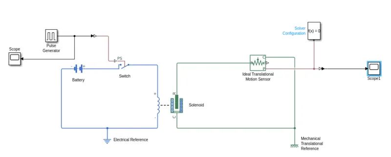
Scope is used to monitor the pulse characteristics of the pulses produced by the pulse generator.
Electrical Reference is used the ground the first circuit.
Scope1 is used to note the motion of the metal arm of the bell during the simulation.
Given below are the parameters set for the pulse generator block
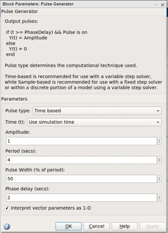
Amplitude, by default, is set at 1
The time Period is set to 4 seconds.
Pulse width, which is specified as a percentage of the Time period, is set to 50%, meaning that the pulse should be produced for only 50% of 4 seconds; i.e 2 seconds.
Phase delay is set at 2, indicating that the pulse will be generated only 2 seconds after the simulation starts.
Results of the simulation:
Given below is the Amplitude Vs Time graph.
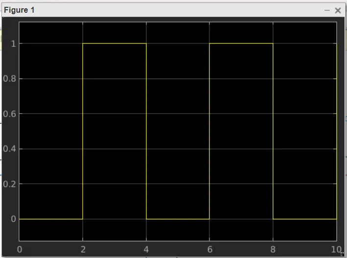
The above graph shows that a pulse of amplitude 1,lasting for a period of 2 seconds, is supplied every 2 seconds to the switch which causes the switch to close and due to which current flows from the battery through to the solenoid, thus producing a linear movement which is detected by an ideal mechanical translations sensor.
The output from the ideal mechanical translations sensor can be seen below in the form of the graph,
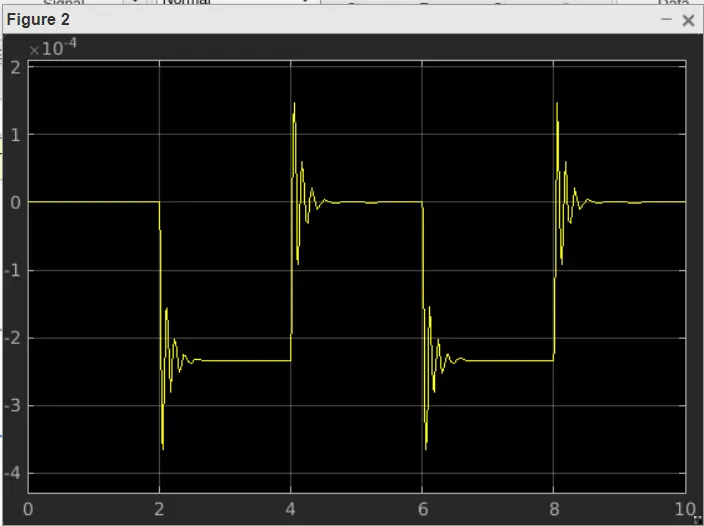
The spikes in the graph represent tranlational mechanical motion. We can see that the spikes correspond to the time when the swtich is closed and current flows through the circuit.
Thus the circuit works as required.
2. Fan Control using Thermistor block :
A basic fan control circuit consists of the following components
1. Battery - power source
2. Thermistor - to control opening and closing of the circuit depending on the temperature conditions.
3. The fan
The term thermistor is a combination of the words 'thermal' and 'resistor'. As the temperature of the thermistor increases the resistance of the thermistor also correspondingly increases or decreases depending on whether it is an NTC (Negative Temperature Coeffcient) or PTC (Positive Temperature Coeffcient) thermistor.
Generally for applications involving temperature dependent circuit control, NTC thermistors are used and is hence used here as well
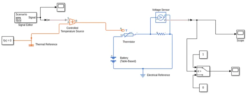
Given below is the simulink model for fan control using a thermistor,
Results of the simulation,
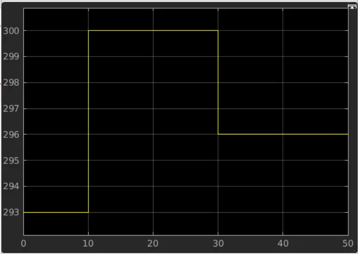
Variation of Input Signal to the controlled temperature source with time
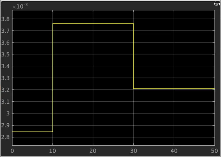
Variation of voltage across the resistor with time
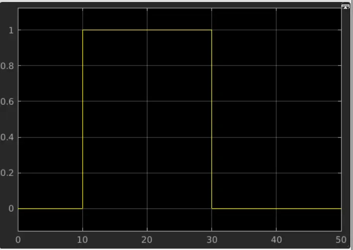
Variation of switch signal with time
The model makes use of a signal editor block to produce the required signal for the controlled temperature source. The signal from the signal editor block needs to be converted into a physical signal to be used by the controlled temperature sourec block and this is done with the help of a Simulink - PS converter.
Based on the physical temperature temperature signal given out by the controlled temperature source to the thermsitor, the thermistor send either an ON signal (denoted by 1 on the switch) or OFF signal (denoted by 0 on the switch).
As can be seen from the graph above when the temperature reaches 300K at t = 10s, the voltage also increases to a value of about 0.00375V. since the voltage in the circuit is less than 0.0033V from t=0 to t=10 and t=30 to t=50, we keep the threshold value of the switch at 0.0033, meaning that when the voltage exceeds 0.0033V the switch gets turned ON. This is done so that the switch is turned on only when the temperature reaches 300K.
From the graphs we can see that the circuit is working as desired.