Door Bell and Fan Simulink Model
Aim:
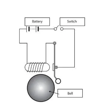
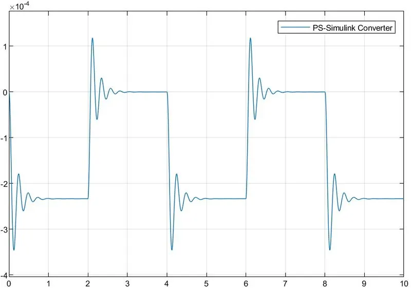
- To Create a Simulink model of a doorbell using solenoid block and to observe the movement of the plunger when the switch is closed for 2 seconds and released.
- To Create a Simulink model using a thermistor to sense the temperature of a heater and to turn on and turn off the fan as per the given conditions.
Conditions:
Temperature source: 20 °C from 0 to 10 seconds
27 °C from 10 to 30 seconds
23 °C from 30 to 50 seconds
Fan Conditions: On if Temperature is above 25 °C else switch off.
1. Doorbell:
Model:
Simulink Block:
Explanation:
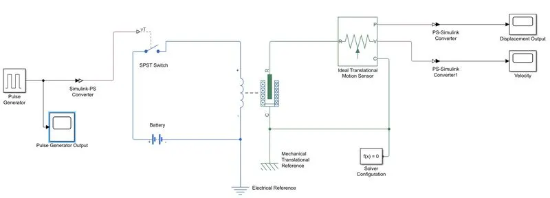
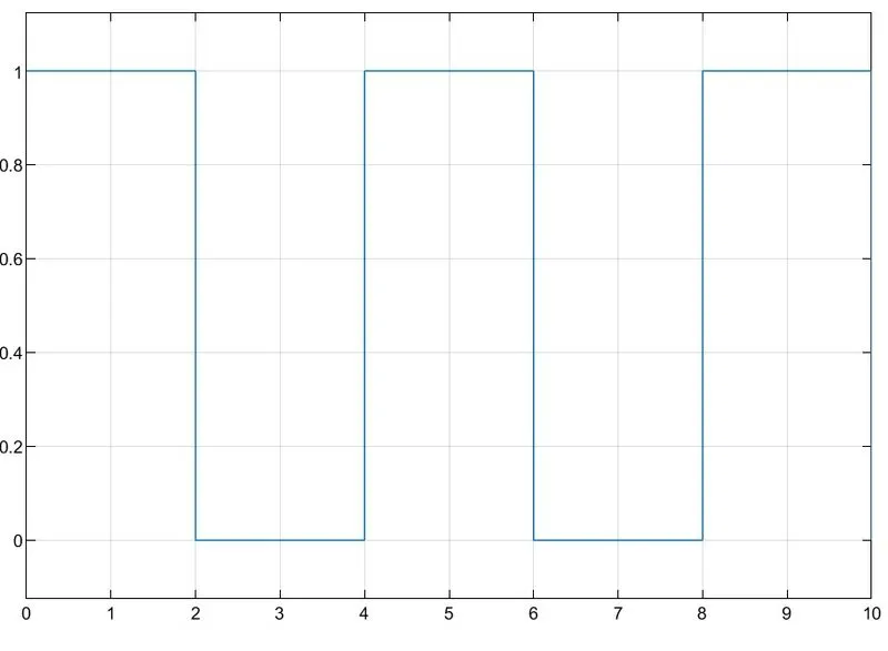
. Pulse generator is used as input with 4 seconds, 50% Cycle for the switch to simulate the bell as shown in the block diagram.
. The pulse generated is a system generated signal and need to be converted to an physical signal using Simulink-PS Converter.
. Solenoid is connetcted to a switch, battery and ground as shown in the block diagram which activates when the electricity passes through.
. Ideal Motion Translational motion sensor is connected to the solenoid to measure the movement.
. A solver configuration is required to compile the simscape block.
. Displacement and velocity is connected to scope block to display the output.
Output:
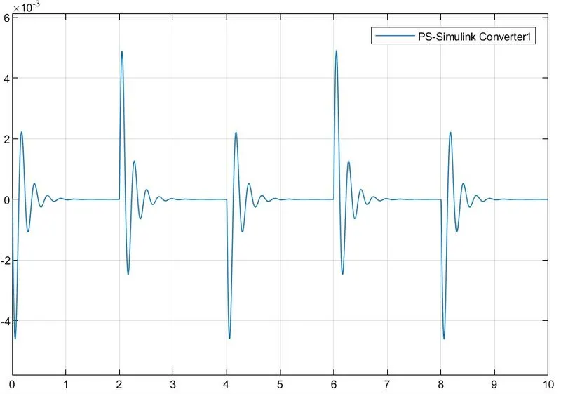
Pulse Generator Output:
Displacement Output:
Velocity Output:
2. Fan Control:
Thermistor:
A thermistor is a resistance thermometer, or a resistor whose resistance is dependent on temperature.
The working principle of a thermistor is that its resistance is dependent on its temperature. We can measure the resistance of a thermistor using an Ohm-meter.
There are two types of thermistors:
- Negative Temperature Coefficient (NTC) Thermistor
- Positive Temperature Coefficient (PTC) Thermistor.
NTC Thermistor
In an NTC thermistor, when the temperature increases, resistance decreases. And when temperature decreases, resistance increases. Hence in an NTC thermistor temperature and resistance are inversely proportional. These are the most common type of themistor.
The relationship between resistance and temperature in an NTC thermistor is governed by the following expression:

Where:
- RT is the resistance at temperature T (K)
- R0 is the resistance at temperature T0 (K)
- T0 is the reference temperature (normally 25oC)
- β is a constant, its value is dependant on the characteristics of the material. The nominal value is taken as 4000.

Simulink Block:
Explanation:
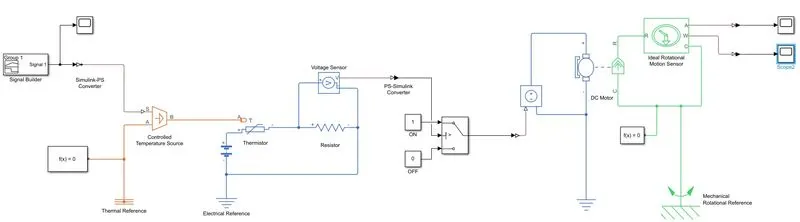
. In the above block a signal builder is used and the plot values are entered as per the conditions given as shown.
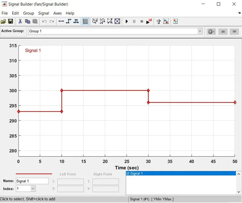
Conditions:
- For '0' to '10' Seconds the Temperature is "293.15K".
- For '10' to '30' Seconds the Temperature is "300.15K".
- For '30' to '50' Seconds the Temperature is "296.15K".
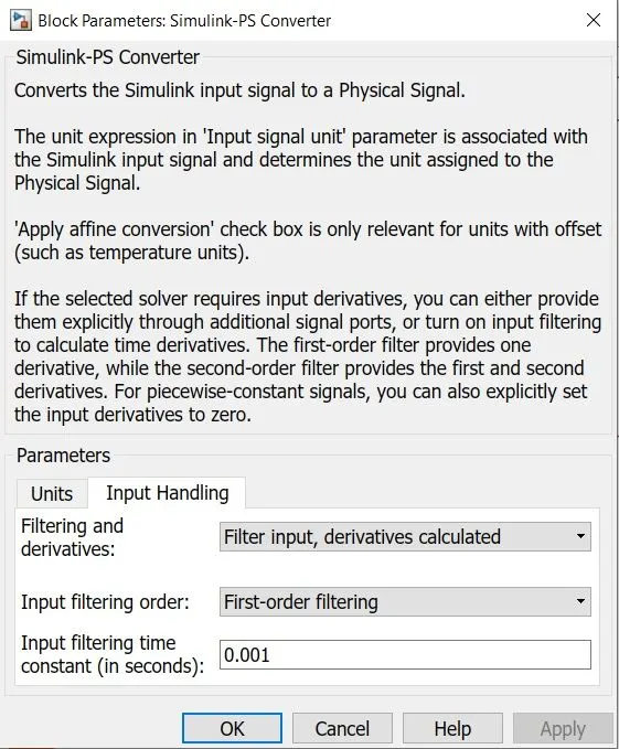
. The signal builder is connected to a Simulink-PS Converter to convert machine signal to physical signal. The Parameters for the block is set to the following as shown. If the following parameter is not set the program does not compile the block and throws an error.
. The Controlled Temperature source is the input for the thermistor.
. Thermistor is connected to a resistor and voltage source which get the 12 V supply from the battery connected.
. The output from the voltage sensor is converted to a machine signal using PS-Simulink converter and is given as an input to the Switch .
. Depending on the input received the Switch block Switches ON or Switches OFF the DC Motor which is the Fan.
. DC Motor is connected to a Ideal Rotational Motion sensor to measure the angular velocity and displacement.
Output:
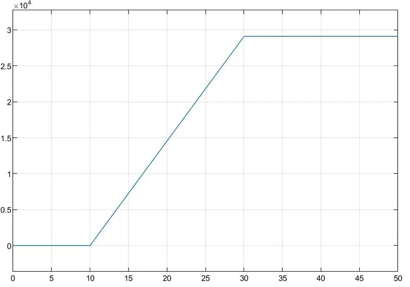
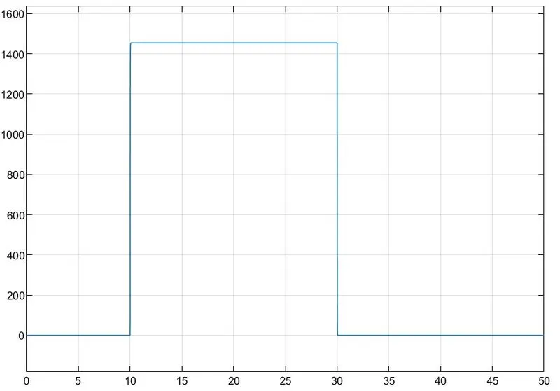
From the above output the Fan is Switched on from 10 Seconds to 30 Seconds when the temperature reaches 27 °C. The Fan is switched OFF when the temperature is 20 °C and 23 °C.