Week -2
Challenge 1: Make a Simulink model of a Doorbell using a solenoid block with the given details:
AIM: To make a Simulink model of a Doorbell using a solenoid block.
THEORY:
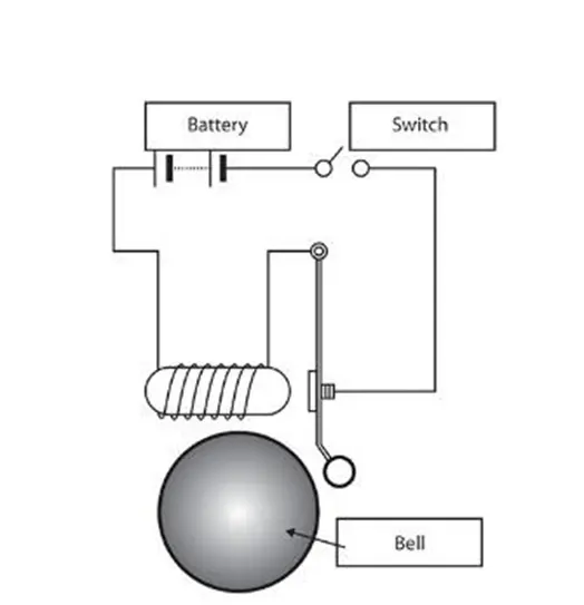
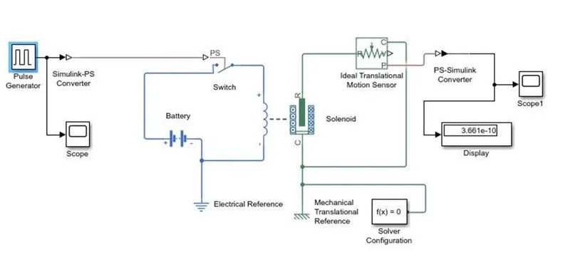
The doorbell operates on the electromagnetic concept. It makes use of a solenoid. When the switch is closed, electricity flows into the solenoid, creating an electromagnetic field. Because of the electromagnetic field, the plunger moves and strikes the bell, producing a sound.
A schematic diagram of the doorbell is shown below.
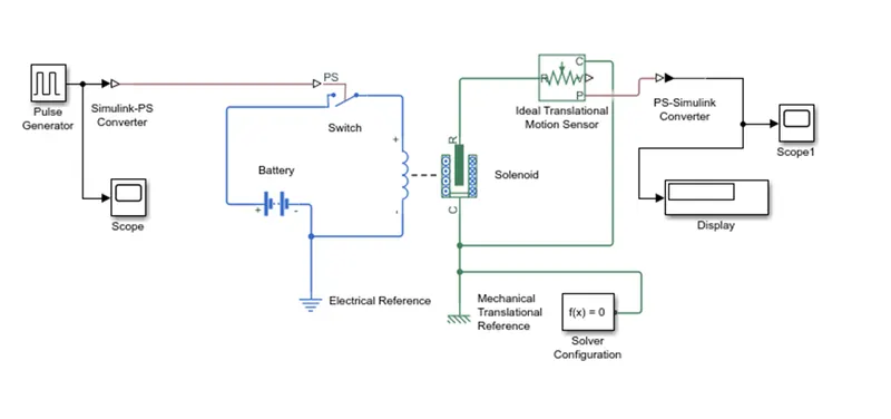
Simulink Model of Door Bell:
STEPS:
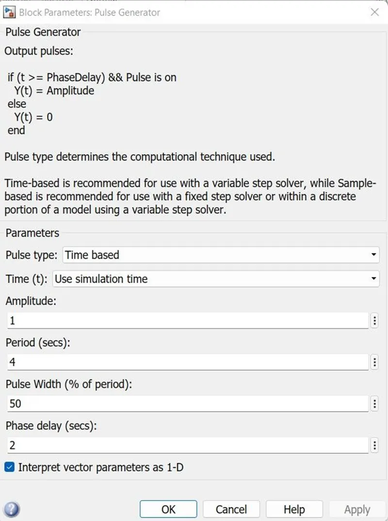
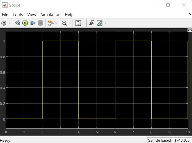
- The pulse generator generates square wave pulses at predetermined intervals. The shape of the output waveform is determined by the block waveform parameters amplitude, pulse width, period, and phase delay.
- The switch block is activated by an external physical signal.
- If the external signal exceeds the threshold, the switch is closed; otherwise, the switch is open.
- The switch's positive terminal is linked to the switch, while its negative terminal is connected to the electrical reference.
- When we connect the solenoid block to the switch and battery, we will have a full electrical circuit.
Mechanical reference is linked to port c. - To monitor the movement of the plunger, the ideal translational sensor is linked to solenoid block R.
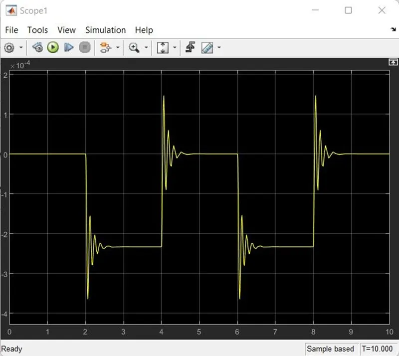
- To obtain the output, the scope is linked to the best translational sensor.
- The physical signal is transformed into a Simulink signal using a PS-Simulink converter.
- Configuration of the solver: In order to simulate any physical network that is represented by a linked simscape block, solver setup information is required.
INPUTS:
Pulse generator block parameter:
Pulse generator input signal:
OUTPUTS:
CONCLUSION:
Hence, the Simulink model of the Doorbell using solenoid was created and studied under given conditions.
*****************************************************************************************************
Challenge 2: Use a thermistor to sense the temperature of a heater & turn on or turn off the fan as per the given conditions.
AIM: To make a Simulink model to turn on and off the fan using a thermistor.
GIVEN CONDITIONS:
- Temperature source: 20 °C from 0 to 10 seconds, 27 °C from 10 to 30 seconds, 23 °C from 30 to 50 seconds.
- Fan conditions: ON if the temperature is above 25 °C, OFF otherwise.
THEORY:
Thermistor: A thermistor is a type of resistor having the characteristic that increases its resistance linearly as temperature rises.
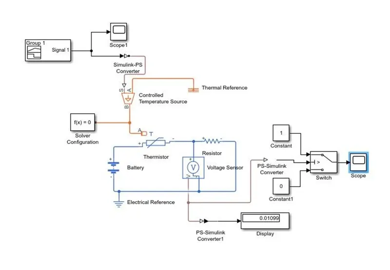
Simulink Model:
Working:
- A battery, a resistor, and a thermistor are used to make a circuit.
- An ideal temperature source is linked to the thermistor, and a voltage sensor is placed across the resistor to detect voltage differences.
- According to the stated circumstances, input signals are delivered to the temperature source.
- The switch receives the voltage sensor's output.
- It uses a DC motor with one end attached to the switch output and the other to a rotating motion sensor.
- To get the motor's angular displacement and velocity, the motion sensor output is linked to a scope.
Input: Using the signal builder, we are applying the given conditions to the Simulink model.
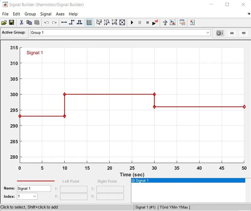
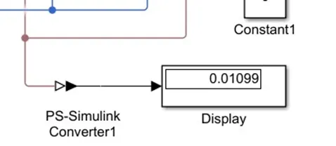
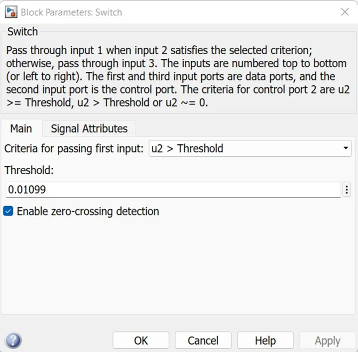
After running the simulation for 50 seconds, the displayed value is again input to the switch for ON and OFF conditions as the threshold value.
Display value:
Switch Parameter:
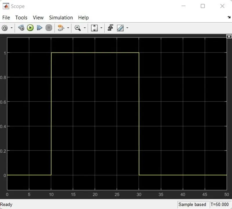
OUTPUTS:
CONCLUSION:
From the graph above, we see that the fan was off for 10 seconds when the temperature was 293 k. When the temperature reaches 298 k, the fan gets turned on for the next 20 seconds. Also, when the temperature falls to 293k, the fan turns off. In this way, the Simulink model to sense the temperature using a thermistor was created and studied.