Week -2
AIM:
- Make a Simulink model of Doorbell using solenoid block Create a situation where the switch is closed for 2 seconds and then released. Observe the physical movement of the plunger.
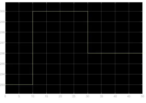
- Use a thermistor to sense the temperature of a heater & turn on or turn off the fan as per the given conditions: Temperature source: 20 °C from 0 to 10 seconds, 27 °C from 10 to 30 seconds, 23 °C from 30 to 50 seconds
Fan conditions: ON if the temperature above 25 °C, OFF otherwise
Study 1
Introduction:
A solenoid is an electromagnetic device consisting of coils and wires, the housing, and the plunger (armature) which is moveable. Whenever the electrical input is given, it forms the magnetic fields which draw the plunger in. So basically, it is the conversion of electrical energy into mechanical energy.
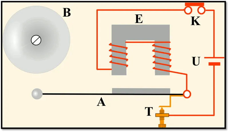
simulink Block Diagram of doorbell using solenoid block:
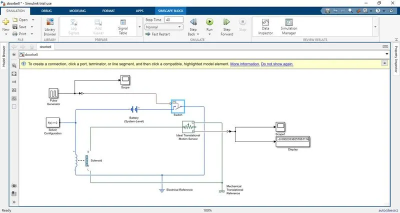
PROCEDURE TO MAKE MODEL:
Add the required blocks battery, switch and solenoid as given in the problem
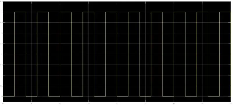
To create a situation where switch is closed for 2 seconds and release, we have to use pulse generator and give period 4 secs and 50% pulse width to make switch on and off for 2 secs
pulse generator is connected to the switch block using simulink -ps converter block and switch block is then connect to the battery to get the supply from battery
positive terminal of battery is connected to solenoid block and electrical blocks are connect to the electrical reference.
solenoid plunger port C connect to the mechanical translational reference
Port R is connected to the ideal translation motion sensor to check the motion and sensor block is connect to ps-simulink
ps-simulink block convert the physical signal to simulink signal
scope block is added to get the result.
RESULTS & OUTPUTS:
The time delay is given 2 secs to the pulse generator to open and close the switch, When the switch is closed, the solenoid receives the electrical power which moves the plunger and produces the bell ring.
Plunger movement: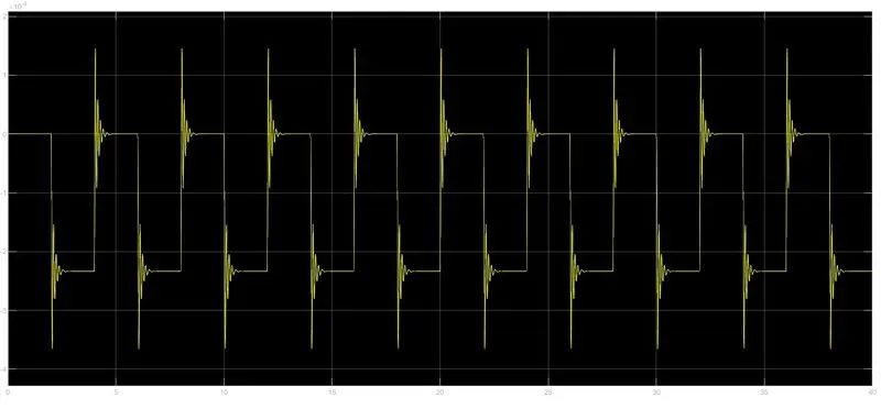
x axis shows the time and y axis shows the displacement of plunger.
it shows the plunger move forward for 2 secs and return for 2 secs.
Conclusion:
Simulink model of Doorbell using solenoid block was Created. Observed the physical movement of the plunger.
STUDY 2:
A thermistor (or thermal resistor) is defined as a type of resistor whose electrical resistance varies with changes in temperature. Although all resistors’ resistance will fluctuate slightly with temperature, a thermistor is particularly sensitive to temperature changes. The working principle of a thermistor is that its resistance is dependent on its temperature. We can measure the resistance of a thermistor using an ohmmeter.
There are two types of thermistors:
Negative Temperature Coefficient (NTC) Thermistor
Positive Temperature Coefficient (PTC) Thermistor
In an NTC thermistor, when the temperature increases, resistance decreases. And when temperature decreases, resistance increases. Hence in an NTC thermistor temperature and resistance are inversely proportional. This is the most common type of thermistor.
In a PTC thermistor the reverse relationship between temperature and resistance. When temperature increases, the resistance increases. And when temperature decreases, resistance decreases. Hence in a PTC thermistor temperature and resistance are inversely proportional. Although PTC thermistors are not as common as NTC thermistors, they are frequently used as a form of circuit protection. Similar to the function of fuses, PTC thermistors can act as current-limiting devices.
BLOCK DIAGRAM:
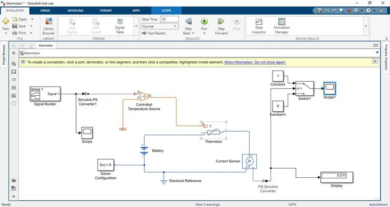
Block diagram Explanation:
Signal builder block is used to create the below signals and values are given in K.
20 °C from 0 to 10 seconds, 27 °C from 10 to 30 seconds, 23 °C from 30 to 50 seconds
it is then connected to the simulink-ps converter to convert signal to physical signal, input handling method is given as first order filter derivatives to avoid error and get smooth output.
output is connected to the port S of controlled temperature source block A port connect to thermal reference and solver configuration block is added.
port B of controlled temp source is connected to the thermistor port A which gives the controlled temp to thermistor block.
Battery and resistor block is connected to the thermistor block
current sensor block added in series to the resistor to calculate the current in electrical blocks are connected to the electrical reference.
the output is given to the switch block where it has 3 ports port 2 is input it validate if it satisfies it gives port 1 as output else port 3 is output.
for greater than 25 deg Celsius the fan must be in off conditions so the voltage for 25 deg Celsius is calculated using the scope 1 block and that voltage value is used as threshold value for switch block.
two constant blocks are defined for fan off and on conditions
scope block is added to get the output whether the fan is off or in position for the total time period of 50 secs.
INPUT RESULTS:
OUTPUTS & RESULTS:
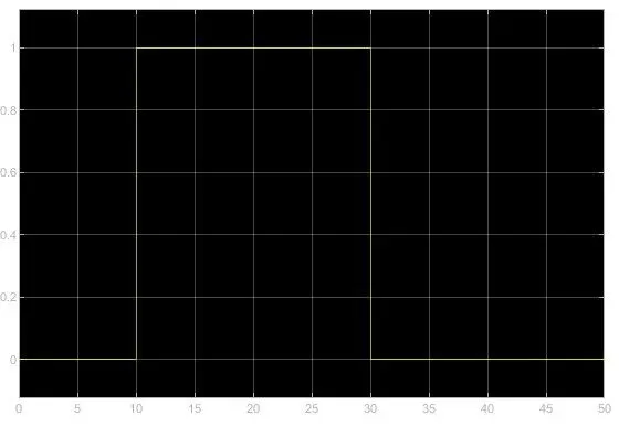
In above graph we can saw form 0-10 sec signal is “0” because in this time the temperature was 20℃ which is below 25℃ mean fan is switch off. After that from 10-30 sec signal is “1” because in this time the temperature was 27℃ which is above 25℃ means fan is switch on. At the end from 30-50 sec signal is “0” because in this time the temperature was 23℃ which is below 25℃ mean fans was switch off.
Conclusion:
We can conclude that from the above output results of our Simulink model for solenoid operated heaters give correct output and satisfy with all input conditions.