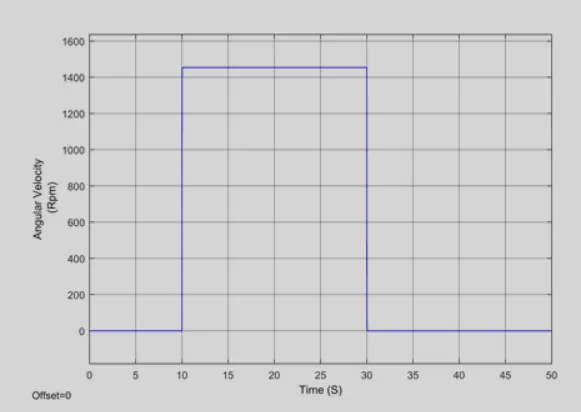
Week -2
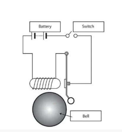
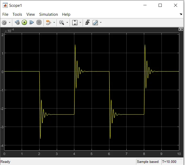
AIM- To make a simulink model of door bell using solenoid block, when switch is closed electromagnet recieves electrical power from battery & pull the metal arm to hit the bell producing sound.
BASIC DIAGRAM OF DOOR BELL.
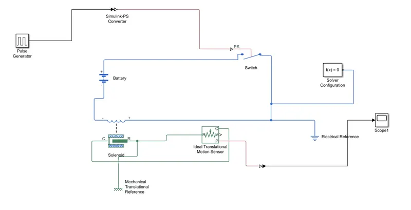
SIMULINK MODEL OF DOOR BELL
OUTPUT
PULSE GENERATOR:-
It generates square wave pulses at regular interval.the block wavform parameters, amplitude, pulse width, period & phase delay, determine the shape of the output waveform.
IDEAL TRANSLATION SENSOR MOTION:-
this blocks measures velocity or displacement in a mechanical translation network.the sensor is ideal since it doent account for inertia,friction , delays and energy.
SOLENOID:-
The solenoid is a type of electromagnet, the purpose of which is to generate a controlled magnetic field through a coil wound into a tightly packed helix. The solenoid is as shown in the figure below. The solenoid is a coil of wire, and the plunger is made of soft iron.
PART 2
AIM:-
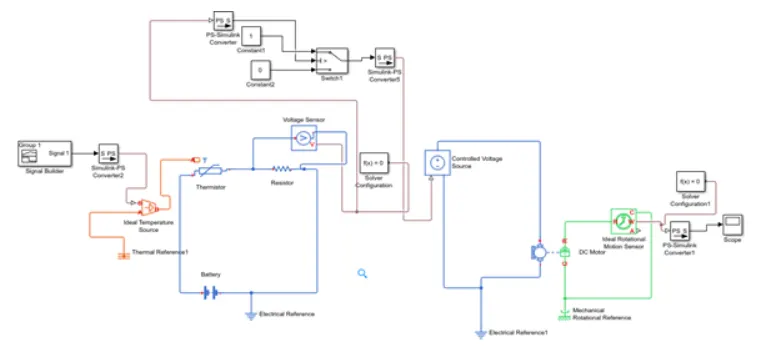
To simulate working of a fan under different conditions using a thermistor in a simulink.
OBJECTIVE:-
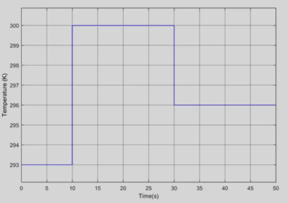
To turn on the fan if the temp. is above 25*c else off. TO use temperature source to simulate temp from 0 to 10 sec at 20*c, from 10 to 30 sec at 27*c and from 30 to 50 sec at 23*c.
INTRODUCTION:-
thermistor is a thrmally sensitive resistor which exhibits a precise & predictable change in resistance proportional to small changes in the surrounding temp.
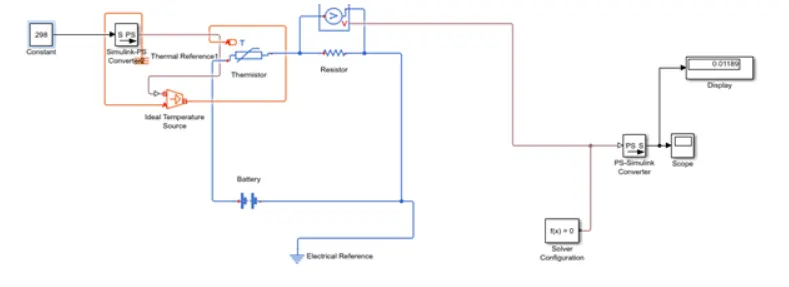
MODEL:-
STEPS:-
- A constant is used to provide the required control temp. in kelvin for the thermistor.
- Its signal is then coverted to physical signal via simulink ps converter and then connected to a controoled temp source which takes the physical signal T to the S port 7 & then its inlet A port is connected to a thermal reference and its output B port is connected to the A thermal port of the thermistor.
- The positive and the negative terminal of the thermistorwere connected to a battery and to a resistor & all the circuit were grounded by electrical references.
- To sense the voltage, a voltage sensor was used and its positive and negative terminals were connected to the respective terminal of resistance.
FULL FAN MODEL:-
INPUT"-
OUTPUT:-