Week -2
SECTION A
AIM- Make a Simulink model of Doorbell using solenoid block.
OBJECTIVE-
- Create a situation where the switch is closed for 2 seconds and then released.
- Observe the physical movement of the plunger.
- Use a thermistor to sense the temperature of a heater & turn on or turn off the fan.
THEORY-
DOORBELL OPERARION-
The heart of a doorbell is an electromagnet. Electromagnets are coils of wire wrapped around a small piece of magnetic metal. When electricity passes through the wire, it creates a magnetic field around the wire.When you press a doorbell button, you complete an electrical circuit that allows household electricity to flow through the doorbell's internal electromagnet. The magnetic field generated by the electromagnet is then used to power a mechanism that creates the doorbell sound.

Now in simulink, we have used following blocks
- Pulse generator- To generate pulse as per our requirement
- Switch- To on/off circuit from power source.
- Battery- To provide power for battery.
- Solenoid- To convert electrical energy into mechanical energy.
- Electrical reference
- scope- To store output.
- Ideal translationa; motion sensor- To detect any motion related with solenoid during simulink.
- Mechanical reference
- PS- simulink converter
- Simulink-PS converter
SIMULINK MODEL-
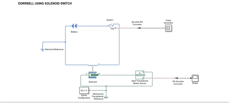
EXPLANATION OF MODEL-
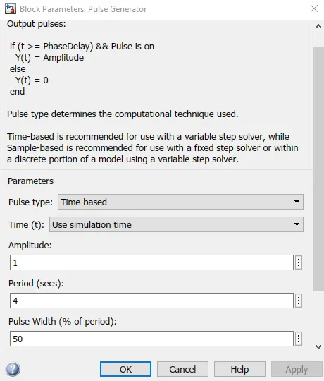
- Pulse generator is used to generate pulse as per our requirement. Pulse parameter has been set like amplitude 1, pulse width 50,period
- Switch block is used to cut off power from circuit.
- Battery is used to provide power for circuit.
- Electrical reference is added and connected to battery.
- Solenoid switch is used as per our requirement.
- Ideal translational motion sensor is used to detect motion of metal.
- Mechanical reference is connected to solenoid and ideal translational motion sensor.
- To observe output scope block is connected.
- Pulse generator parameter has been set as following
OUTPUT-
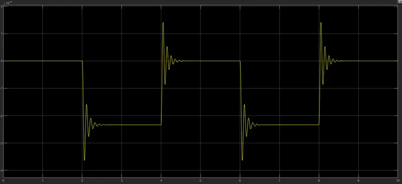
From above result, The motion is generated for 2 sec and staying idle for 2 sec as per our requirement. This loop is getting repeated for respective simulation time.
Due to magnetic field, motion is transferred to metal arm and its connected to doorbell, which is producing sound for bell.
SECTION 2-
AIM- Use a thermistor to sense the temperature of a heater & turn on or turn off the fan.
OBJECTIVE- Temperature source: 20 °C from 0 to 10 seconds, 27 °C from 10 to 30 seconds, 23 °C from 30 to 50 seconds.
Fan conditions: ON if the temperature above 25 °C, OFF otherwise.
THEORY-
A thermistor is a resistance thermometer, or a resistor whose resistance is dependent on temperature. The term is a combination of “thermal” and “resistor”. It is made of metallic oxides, pressed into a bead, disk, or cylindrical shape and then encapsulated with an impermeable material such as epoxy or glass.There are two types of thermistors: Negative Temperature Coefficient (NTC) and Positive Temperature Coefficient (PTC). With an NTC thermistor, when the temperature increases, resistance decreases. Conversely, when temperature decreases, resistance increases. This type of thermistor is used the most.A PTC thermistor works a little differently. When temperature increases, the resistance increases, and when temperature decreases, resistance decreases. This type of thermistor is generally used as a fuse.Typically, a thermistor achieves high precision within a limited temperature range of about 50ºC around the target temperature. This range is dependent on the base resistance.
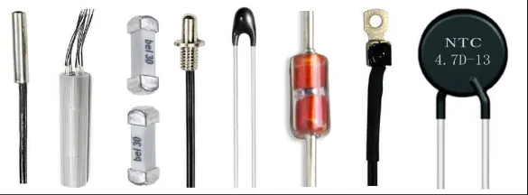
The main use of a thermistor is to measure the temperature of a device. In a temperature controlled system, the thermistor is a small but important piece of a larger system. A temperature controller monitors the temperature of the thermistor. It then tells a heater or cooler when to turn on or off to maintain the temperature of the sensor.
In the diagram below, illustrating an example system, there are three main components used to regulate the temperature of a device: the temperature sensor, the temperature controller, and the Peltier device (labeled here as a TEC, or thermoelectric cooler). The sensor head is attached to the cooling plate that needs to maintain a specific temperature to cool the device, and the wires are attached to the temperature controller. The temperature controller is also electronically connected to the Peltier device, which heats and cools the target device. The heatsink is attached to the Peltier device to help with heat dissipation.
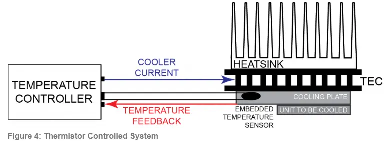
The job of the temperature sensor is to send the temperature feedback to the temperature controller. The sensor has a small amount of current running through it, called bias current, which is sent by the temperature controller. The controller can’t read resistance, so it must convert resistance changes to voltage changes by using a current source to apply a bias current across the thermistor to produce a control voltage.
The temperature controller is the brains of this operation. It takes the sensor information, compares it to what the unit to be cooled needs (called the setpoint), and adjusts the current through the Peltier device to change the temperature to match the setpoint.
The location of the thermistor in the system affects both the stability and the accuracy of the control system. For best stability, the thermistor needs to be placed as close to the thermoelectric or resistive heater as possible. For best accuracy, the thermistor needs to be located close to the device requiring temperature control. Ideally, the thermistor is embedded in the device, but it can also be attached using thermally conductive paste or glue. Even if a device is embedded, air gaps should be eliminated using thermal paste or glue.
Required Blocks for this model-
1) Constant-
Output the constant specified by the 'Constant value' parameter. If 'Constant value' is a vector and 'Interpret vector parameters as 1-D' is on, treat the constant value as a 1-D array. Otherwise, output a matrix with the same dimensions as the constant value.
2) Simulink - PS converter-
Converts the unitless Simulink input signal to a Physical Signal.The unit expression in 'Input signal unit' parameter is associated with the unitless Simulink input signal and determines the unit assigned to the Physical Signal.
3) Solver configuration-
Defines solver settings to use for simulation.
4)Controlled Temperature Source-
This block represents an ideal energy source in a thermal network that can maintain a controlled temperature difference regardless of the heat flow rate. The temperature difference is set by the physical signal port S. A positive temperature difference causes the temperature at port B to be greater than the temperature at port A.
5) Thermistor-
This block represents an NTC thermistor using the B-parameter equation. The resistance at temperature T is given by R(T) = R0*exp(B*(1/T-1/T0)) where R0 is the Nominal resistance at the reference temperature T0, and B is the Characteristic temperature constant. The temperature T of the thermistor is governed by the equation m*c*dT/dt = Q where Q is the net heat flow into port A, m is the mass and c is the lumped specific heat capacity. The thermal mass m*c is calculated from the Thermal time constant t_c and the Dissipation factor K_d using the equation m*c = K_d*t_c.
6)Battery-
This block models a battery. If you select Infinite for the Battery charge capacity parameter, the block models the battery as a series internal resistance and a constant voltage source. If you select Finite for the Battery charge capacity parameter, the block models the battery as a series internal resistance plus a charge-dependent voltage source defined by:
V = Vnom*SOC/(1-beta*(1-SOC))
where SOC is the state of charge and Vnom is the nominal voltage. Coefficient beta is calculated to satisfy a user-defined data point [AH1,V1].
7) Register-
The voltage-current (V-I) relationship for a linear resistor is V=I*R, where R is the constant resistance in ohms.The positive and negative terminals of the resistor are denoted by the + and - signs respectively. By convention, the voltage across the resistor is given by V(+)-V(-), and the sign of the current is positive when flowing through the device from the positive to the negative terminal. This convention ensures that the power absorbed by a resistor is always positive.
8) Voltage sensor-
The block represents an ideal voltage sensor, that is, a device that converts voltage measured between any electrical connections into a physical signal proportional to the voltage.Connections + and - are conserving electrical ports through which the sensor is connected to the circuit. Connection V is a physical signal port that outputs voltage value.
9) Switch-
Pass through input 1 when input 2 satisfies the selected criterion; otherwise, pass through input 3. The inputs are numbered top to bottom (or left to right). The first and third input ports are data ports, and the second input port is the control port. The criteria for control port 2 are u2 >= Threshold, u2 > Threshold or u2 ~= 0.
10)Display-
Display input values. If the incoming signal is of type string, the 'Numeric display format' parameter selection does not affect the display of the string.
11) PS-Simulink converter-
Converts the input Physical Signal to a unitless Simulink output signal.The unit expression in 'Output signal unit' parameter must match or be commensurate with the unit of the Physical Signal and determines the conversion from the Physical Signal to the unitless Simulink output signal.'Apply affine conversion' check box is only relevant for units with offset (such as temperature units).
MODEL-
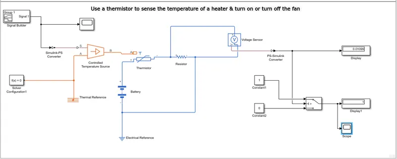
EXPLANATION-
- We have used thermister,battery,switch, register to create basic fan model, however to convert this into simulink modeling we have used required block as shown in figure.
- For thermister we have taken thermister block and positive terminal of this block is connected to battery block.
- Register block is used to represent register, negative terminal of register is connected with thermister.
- Electrical reference block is used to provide earthing to circuit.
- Voltmeter is used to represent voltmeter and this voltmeter block is connected in series with register.
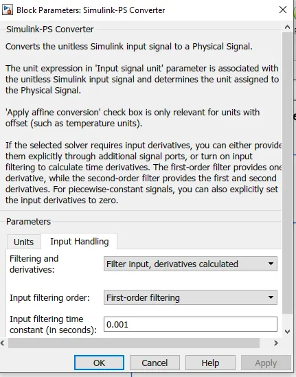
- To convert signal into physical signal we have used simulink-ps converter block at starting. To get proper and smooth output, we have to change input handling parameter of this block. changes has been shown in below figure.
- Controlled temperature source block is used which is provide specific temperature during more heat flow.
- Now for this case fan need to get on and off at particular temperature. so, for this we have used signal builder block. This signal provide any type of signal required for us.
- NOw, to set temperature value at different time, we have to open signal builder block. As per our requirement we have to do configuration in block setting.
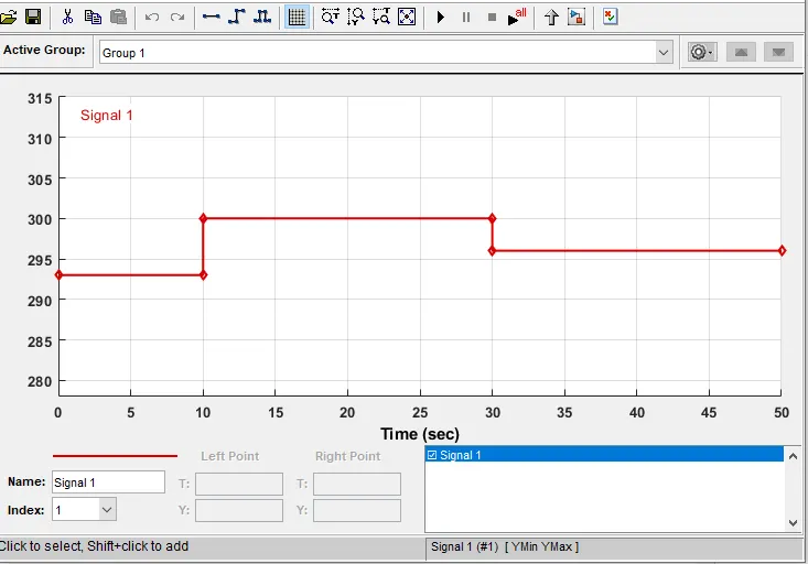
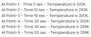
- All configuration has been set as above. To set this we have to use custom option which present in signal option at top. By cllicking on each point we have to set values for T and Y as per our requirement.
- We have created signals according above figure,we have give this signal to controlled temperature source block but before this we have to convert this signal into physical signal by using simulink-ps converter.
- Now port B of controlled temperature source block to port A of thermistor block and port A of controlled temperature source block is connected to thermal reference block.Now, in controlled temperature source block a positive temperature difference causes the temperature at port B to be greater than temperature at port A.
- Now, the output of voltage sensor block is conneted to scope block and before this we have to convert physical signal into simulink signal by using ps-simulink converter.
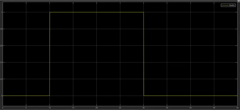
- As per our requirement fan has to start by 25 degree c , i.e 298k, from the graph when voltage is more than 0.010 then fan has to get on and when is below then its should get off.
- From this above logic fan gets on and off. To this we have used switch block, that routes the signal according to conditions provided.
- Center port of switch block is connected to PS-simulink converter which gives voltage values.Top port of switch block is connected to constant value 1 and bottom port is connected to constant value o.
- The center port of switch block is the condition input which means that when the value from voltage sensor block is more than the thershold value in switch block then it will pass the value 1 which we have specified in the top port of switch block.If the value from switch block is less than thersold value in the switch block then it will pass value 0 which is specified in botttom port of switch block.Hence it is act as thermistor in circuit.
- By doubble clicking on switch block we can set thershold value Fan will be on when temperature is 300 k only. we have set thershold value at 0.010 so, when voltage is more than 0.010 then it will pass 1 value and our fan gets on. On other side when voltage is less than 0.010 than it will pass o value and our fan remains off.
- Output of switch block is connected to another scope block where we can se graph for this model.
FINAL OUTPUT-
CONCLUSION-
- Both our objectives are successfully achieved.
- To simulating any other physical device same approch is used.
- In out heater model fan temperature is sensed by thermister.
REFERENCE-
https://www.teamwavelength.com/thermistor-basics
mathwork