Week -2
1. Aim:-
- Make a Simulink model of Doorbell using solenoid block.
- Use a thermistor to sense the temperature of a heater & turn on or turn off the fan according to temperature.
2. Questions & Solutions
Q1. To make a simulink model of Doorbell using Solenoid block.
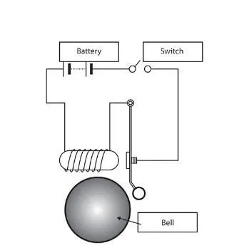
- In the above arrangement, when the switch is closed the electromagnet receives electrical power from the battery and pulls the metal arm to hit the bell producing sound.
- Create a situation where the switch is closed for 2 seconds and then released. Observe the physical movement of the plunger.
- Assume remaining parameters.
Solution1.
- Theory:
- The circuit of the door bell using solenoid block is as shown in above figure.
- When close the switch we complete the circuit then the electric current is flown through the circuit.
- After that, the electromagnet gets charged, and then it acts like a magnet due to which it pulls the nears metal clip towards it.
- As the metal clip towards the magnet, the extended part of the metal clip hits the gong and creates the sound.
- Which we refer to as the sound of a bell.
Following is the simulation module for door bell using solenoid block.
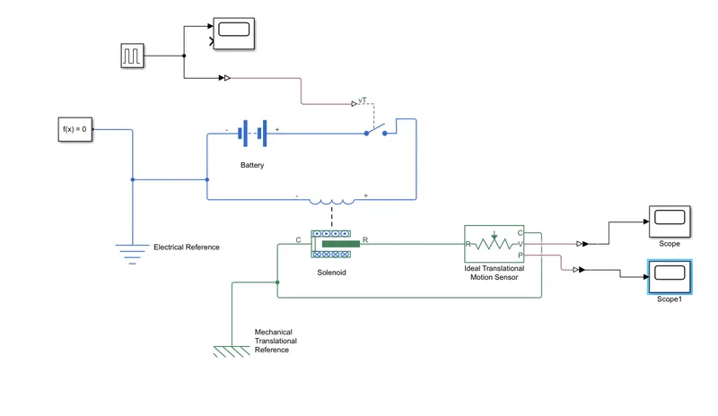
- Pulse Generator:- The pulse generator block generates square wave pulses at regular intervals.
- Scope:- Displays signals generated during simulation.
- Simulink-ps converter:- Converts the simulink input signal to physical signal.
- SPST Switch:- The block represents a single-pole-single-throw(SPST) switch controlled by an external control signal vt. If vt is greater than the threshold, then the switch is closed, otherwise , the switch is open.
- Battery:- It is a stored electrical source for the electric circuit.
- Electrical Reference:- The electrical reference block is represents an electical ground.
- Solenoid:- The solenoid block represents the electrical characteristics and generated force for the solenoid. This solenoid block represents port R moves towards port C.
- Mechanical Translational Reference:- The Mechanical Translational Reference block represents a reference points, or frame, for all Mechanical translational ports.
- Ideal Motion Translational Sensor:- The Ideal Motion Translational Sensor block represents a device that coverts and acrooss variable measured between two mechanical translational nodes into a control signal proportional to velocity or positions.
- Solver Configuration:- The solver configuration block specifies the solver parametres that your model needs before you can begin the simulation.
- PS_Simulink converter:- Converts the inut physical signal to a simulink output signal.
- Working of Model
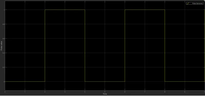
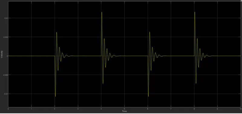
- Pulse Generator creates an input signal of pulse with 1 unit amplitude, 4 sec period, having 50% pulse width with 2-sec delay for the model.
- Then scope compare the input and output of the model.
- After the electric circuit is closed the current flown from the circuit and then it energies the solenoid connected to the battery.
- As the solenoid is charged it pulls the port R towards port C( which refers to us as the ringing of a bell.)
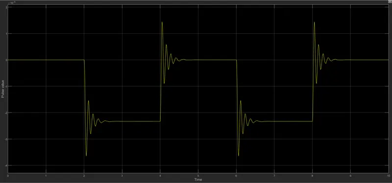
- A mechanical transaltional reference is attached to the port R of the solenoid to understand the positions and velocity of the plunger of the solenoid.
- To record the positions and velocity PS-Converter converts the physical signal to a simulink signal and then using the scope block we record it for the simulink duration.
Results:-
1. Plot pulse value v/s Time
2. Plot pulse value v/s Time
3. Plot Velocity v/s Time
Q2. Use a thermistor to sense the temperature of a heater & turn on or turn off the fan as per the below conditions:
- Temperature source: 20 °C from 0 to 10 seconds, 27 °C from 10 to 30 seconds, 23 °C from 30 to 50 seconds
- Fan conditions: ON if the temperature above 25 °C, OFF otherwise
Theory
A thermistor is a type of resistor whose resistance strongly depends on temperature. The word thermistor is a combination of words “thermal” and “resistor”. A thermistor is a temperature-sensing element composed of sintered semiconductor material and sometimes mixture of metallic oxides such as Mn, Ni, Co, Cu and Fe, which exhibits a large change in resistance proportional to a small change in temperature. Pure metals have positive temperature coefficient of resistance, alloys have nearly equal zero temperature coefficient of resistance and semi conductors have negative temperature coefficient of resistance.
Thermistors can be classified into two types:
- Positive temperature coefficient (PTC) thermistor:-resistance increase with increase in temperature.
- Negative temperature coefficient (NTC) thermistor:-resistance decrease with increase in temperature.
The thermistor exhibits a highly non-linear characteristic of resistance vs. temperature.
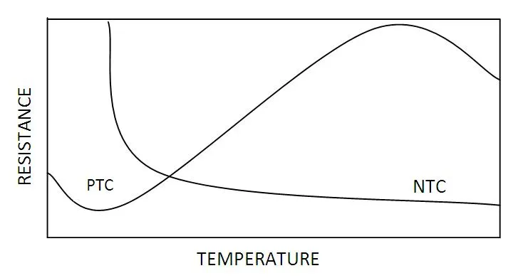
PTC thermistors can be used as heating elements in small temperature controlled ovens. NTC thermistors can be used as inrush current limiting devices in power supply circuits. Inrush current refers to maximum, instantaneous input current drawn by an electrical device when first turned on. Thermistors are available in variety of sizes and shapes; smallest in size are the beads with a diameter of 0.15mm to 1.25mm.
There are two fundamental ways to change the temperature of thermistor internally or externally. The temperature of thermistor can be changed externally by changing the temperature of surrounding media and internally by self-heating resulting from a current flowing through the device.
The dependence of the resistance on temperature can be approximated by following equation,
 ---------------------------------- (1)
R is the resistance of thermistor at the temperature T (in K)
R0 is the resistance at given temperature T0 (in K)
β is the material specific-constant
The material specific-constant of a NTC thermistor is a measure of its resistance at one temperature compared to its resistance at a different temperature. Its value may be calculated by the formula shown below and is expressed in degrees Kelvin (°K)
- Following is the simulation for Using a thermistor to sense the temperature of a heater & turn on or turn off the fan as per the below conditions:
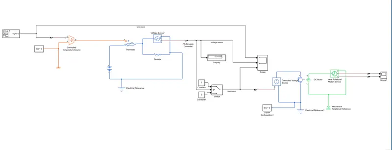
- In the above model simulation blocks used:
- Controlled Temperature source
- Thermistor
- Resistor
- Voltage sensor
- Battery
- Switch
- Electrical reference
- Universal motor
- Mechanical Rotational Motor
- Ideal Rotational motion sensor
- Solver configuration
- PS-Simulink converter
- Scope
- Working of subsystem model
- According to the given conditions we need to build the temperature source 20deg centigrate from 0 to 10 seconds, 27deg centigrate from 10 to 30 seconds, 23deg centigrate from 30 to 50 seconds.
- Then we take the products of constants and their respective pulse generator.
- By adding them we create the signal needed according to the given conditions.
- And we add another constant value 273.15 which converts deg celcius value to deg kelvin.
- Working of the model.
- The temperature source subsystem model provides the temperature to the controlled temperature source, according to the inputs it provides the surrounding temperature condition to the thermostat.
- The thermostat is connected in a closed circuit with a battery and a resistor connected in a series combination with it.
- As the tempoerature increases the thermostat resistance value decreases and the overall current in the circuit increases, which leads to an increase in the voltage around the resistor of 10 ohms.
- We note the voltage around the resistor when the temperature is about 25deg celcius which is 2.373v
- By using PS-SImulink converter we convert a physical signal from the voltage sensor into a simulink signal and record it using a scope block to understand how voltage varies with temperature.
- The voltage sensor signal is also sent to switch whose threshold value 2.273v, i.e. When the temperature goes above 25deg celcius the switch is closed & completes the circuit.
- As the universal motor is connected in series with the switch and the battery, it gets on only when the temperature is above 25 deg celcius.
- To verify the outcome of the universal motor we have attached the ideal rotational motion sensor to iy.
- Now the PS-SImulink converter converts the physical signal from the rotational sensor and converts it into a simulink signal which is then used to record the angular velocity and the angle of the univerdal motor.
Results:-
- Temperature v/s time
- Voltage sensor v/s time
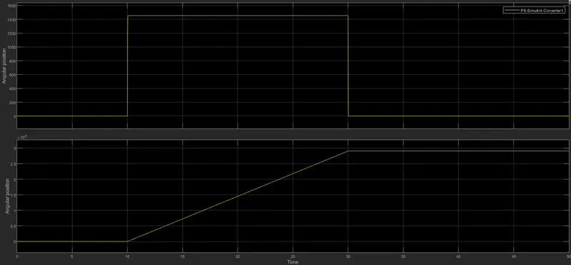
- Angular velocity v/stime
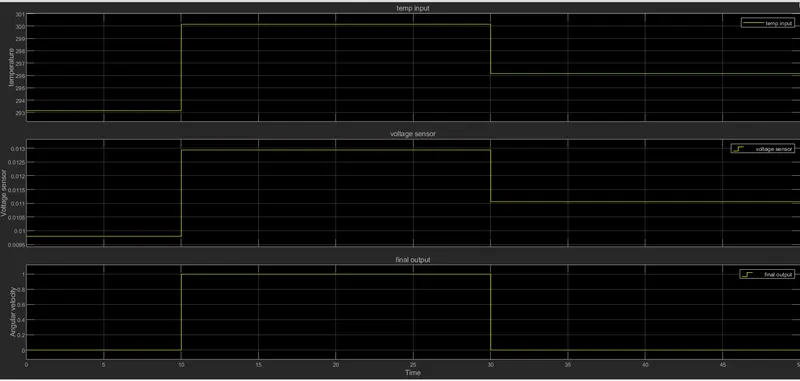
- Angular positions v/s time
Conclusion:-
- We have completed and run the model of the doorbell using solenoid block.
- Thus bell is rung for every alternate 2 seconds.
- We have completed and run the model of using a thermistor to sense the temperature of a heater & turn on or turn off the fan as per conditions.
- Thus fan is turned on only when the temperature is above 25 deg Celcius.
- We observe the title