Week -2
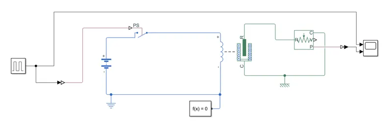
1) Making a Simulink model of Doorbell using solenoid block
blocks used:
1) pulse generator: pulse generator creates pulse wave which is used as an input to turn the sitch on and off. We change the parameters based on our requirment. here time period is set for 4 seconds and pulse width (% of period) as 50
2) Simulink-PS and PS-simulink: is used to connect simulink block to pysical block and vice versa
3) Switch: this switch is from electrical library and not simulink library. the switch controlled by an external physical signal. If the external physical signal PS is greater than the threshold, then the switch is closed, otherwise the switch is open.
4) Battery: to supply the desired voltage
5) Solenoid : solenoid converts electrical energy to mechanical work. here supply to the solenoid valve is turned on and off. the generated mechanical work can be used to ring a bell
6) Ideal Translational Motion Sensor: This block measures velocity or displacement in a mechanical translational network. The physical signal ports V and P report the velocity and position, respectively, of port R relative to port C. The measured velocity is positive when the velocity at port R is greater than the velocity at port C.
7) Scope: scope is used to display input and output results
8) Reference block: our model consists of mechanical and electrical blocks so we use elecrical and mechanical reference.
9) Solver configuration: to define the solver settings we use solver configuration block
Simulink model:
Output and Observation:
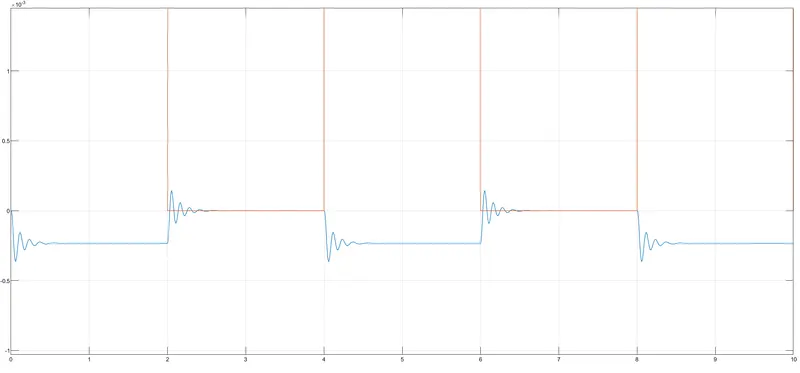
The blue line in the graph is the output from the sensor connected to the solenoid. We can see that wave forms are generated every 2 seconds which resembles the solenoid moving to and fro.
if a hammer is attached to the solenoid and a gong placed infront of it we can create the Bell ringing sound
2. Use a thermistor to sense the temperature of a heater & turn on or turn off the fan as per the below conditions:
Temperature source: 20 °C from 0 to 10 seconds, 27 °C from 10 to 30 seconds, 23 °C from 30 to 50 seconds
Fan conditions: ON if the temperature above 25 °C, OFF otherwise
Blocks used
1) Signal builder: Used to build signal based on the required parameters, here we set X axis time limit to 50 seconds and Y axis limit from -0.1 to 30
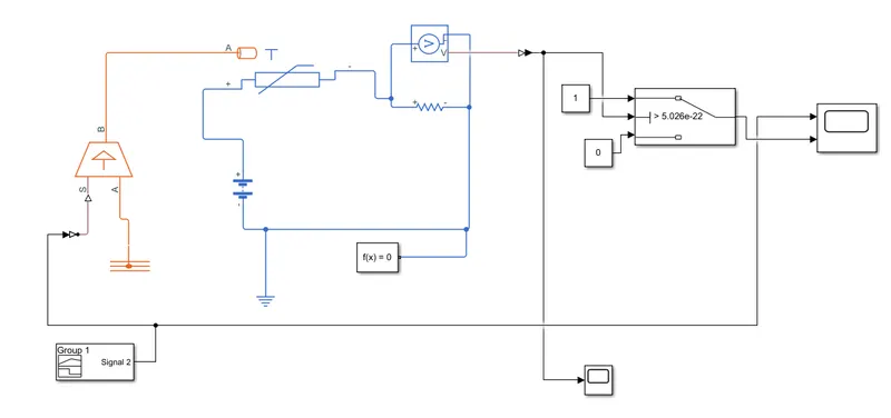
2) Controlled temperature source: This block can maintain a controlled temperature difference regardless of the heat flow rate. The temperature difference is set by the physical signal port S. A positive temperature difference causes the temperature at port B to be greater than the temperature at port A. signal builder output is connected to physical signal port
3) Thermistor: thermistor block represents an NTC thermistor.Here the resistance decreases when the temperature is increased
4) Battery: used to supply voltage
5) Voltage sensor: used to sense voltage
6) Resistor: Acting as a load
7) Constant: used to create constant 0 and 1 which is given as input to the switch (1 being on condition and 0 off)
8) Switch:
9) Reference block: our model consists of thermal and electrical blocks so we use elecrical and mechanical reference.
10) Solver configuration: to define the solver settings we use solver configuration block
12) Scope: scope is used to display input and output signal. Additional scope is used to determine the threshold value to control the switch
Simulink model:
Additional explanation:
Thermistor:
A thermistor is a semiconductor that has a resistance capacity more than a conducting material and less than
insulating material. Its electrical resistance varies with the change in the temperature or thermally sensitive resistor.
There are mainly two types of thermistors
1)Negative Temperature Coefficient (NTC)
2)Positive Temperature Coefficient (PTC).
Thermistor’s relation with temperature also depends on the material in which it is made. A negative temperature
coefficient (NTC) thermistor will decrease its resistance value when temperature increases whereas a Positive
temperature coefficient will increase its resistance when temperature increases.
NTC thermistors are widely used in industries for different applications like temperature measurements, temperature
control, and different applications NTC is an integral part of. PTC is mostly seen in circuit protection, current-limiting
resistors. Here we use only NTC
Why resistor is connected across the voltage sensor?
Voltage sensor has high impedance so the circuit acts as an open circuit, hence we add a load to close the circuit
Finding the threshold value for switching on and off
we connect a scope to the voltage sensor to obtain threshold value. this threshold value is given for the switch
Signal builder parameters:
as mentioned in block explantion after setting the limits we manually drag and move the graph to achieve our desired parameters the resulted pulse is shown below
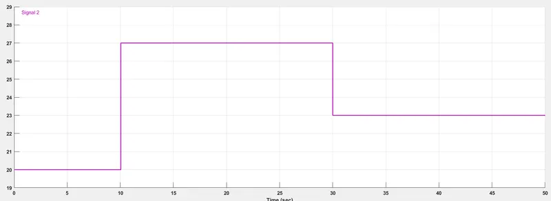
note: simulation runtime is set for 50 seconds since our desired parameters have values till 50 seconds
Output and Observation:
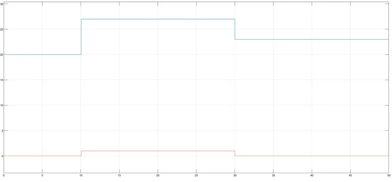
by giving the correct threshold value to the switch, we were able to switch on and off when the temperature was above 25 deg.c as seen above
Reference: