Week -2
AIM:
- To make a simulink model of door bell using solenoid block.
- To make a simulink model using a thermistor to sense the temperature of a heater and turn on or turn off the fan.
OBJECTIVE:
- For making the doorbell using solenoid block with the following details, Create a situation where the switch is closed for 2 seconds and then released. Observe the physical movement of the plunger.
- Use a thermistor to sense the temperature of a heater and turn on or turn off the fan as per the condition, Temperature source: 20°C from 0 to 10 seconds, 27°C from 10 to 30 seconds, 23°C from 30 to 50 seconds. Fan conditions: On if the temperature above 25°C, Off otherwise.
1.Doorbell using solenoid block
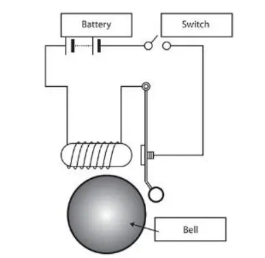
Basic components used are:
- Battery
- Switch
- Solenoid
- A bell with plunger
SIMULINK MODEL:
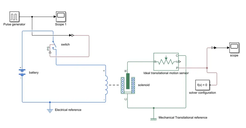
From the above simulink block we made a doorbell, Simulink blocks we used are pulse generator, switch, battery, solenoid, electrical reference, ideal transilational sensor, mechanical transilational reference, solver configuration, 2 scopes, PS to simulink converter and a simulink to PS converter.
We can explain the simulink block by first a solenoid block is taken from the library browser and this is connected to a battery via positive and negative terminals. And a switch block i placed in between the solenoid block and battery block. Now for the switch to operate we need to provide a physical signal through PS port in the switch block. And the provided physical signal should be greater than the threshold of the switch, for switch being closed, or else it will open. After doing all these the whole connection will pass through a electrical reference block, which is to represent the earthing of the circuit. And then, in the solenoid block R and C are two variables which is to represent the plunger and fixed point. Then the R is connected to the R of the ideal transilational motion sensor. Now in the ideal transilational motion sensor output is given by V and P it is velocity and position respectively. And here we only need the change in position of the plunger so output of P only taken. And cycle of the sensor is from C to R and it continues, And the C of the sensor is connected to a Mechanical Transilational reference, And also the C of the solenoid block is also connected to the mechanical transilational reference. From this a output from the plunger will be plotted in the scope block. To provide a physical signal for operating the switch, we used the pulse generator block.
For this pulse generator block we gives the parameters as, for period value as 4, pulse width as 50, phase delay as 2 and amplitude as 1. and this pulse generator is connected to scope and we get the graph as,
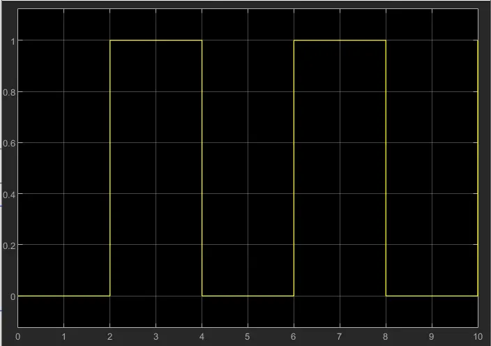
This is the graph of the scope 1, in the x axis it shows the time and in the y axis it is amplitude.
And the ideal transilational motion sensor is connected to a scope and a solver configuration is also connected to the path, And now by runing the model the result of the scope will be a graph as,
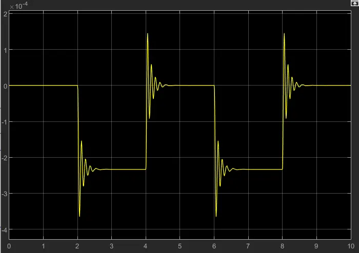
This is the grapg of the scope, in the x axis it is time and in the y axis it is position of plunger.
2.FAN OPERATION USING THERMISTOR:
Basic components used are:
- Thermistor
- Battery
- Fan
- Transistor
- Resistor
SIMULINK MODEL:
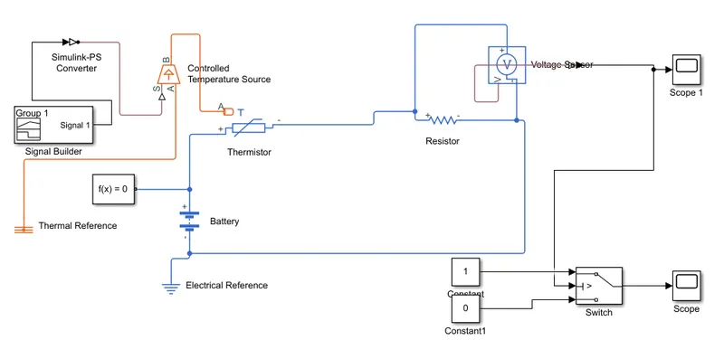
From the above simulink block we made a cooling fan model, Here we use simulink blocks they are; Signal builder, Controlled temperature source, thermistor, battery, resistor, voltage sensor, switch, scopes, thermal and electrical reference and simulink-PS converter.
First we add a thermistor block and then we add a battery to the model and connected from positive of the battery to positive of the thermistor, and then a resisitor is added and its positive port to the negative port of the battery, and electrical refrence is added to represent the earthing, and then a voltage sensor is added to parallel to the resistor. And now to control the fan by on and off at different temperature we want to add controlled temperature source, and a signal builder is added to send the temperature to the controlled temperature source. And we have to add the values in the signal builder as per the requirement. The input values are 20°C(293.15k) from 0 to 10 seconds, 27°C(300.15K) from 10 to 30 seconds, 23°C(296.15K) from 30 to 50 seconds. By adding the values to the signal builder we get the graph as,
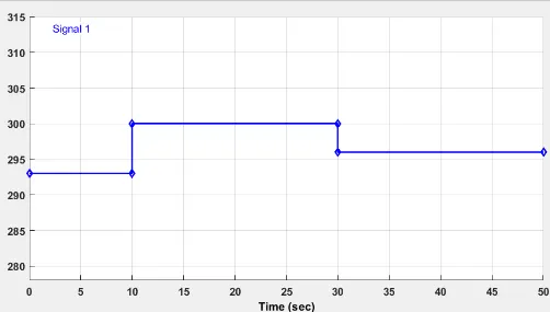
From the graph it is clear that different temperature are given at different time.
And then the port B of the controlled temperature source block is connected to port A of the thermistor block and port A of the controlled temperature source block is connected to the thermal reference. And now the output of the voltage sensor is connected to the scope block and a PS-Simulink converter is placed between it.And the scope block shows the graph as,
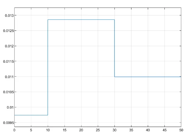
From the graph it is clear that how the voltage is changing with change in temperature.
To switch the fan ON and OFF we used switch block to the model. And here the center port of the switch is connected to the PS-Simulink converter. The top port of the switch block is connected to the constant block of value 1 and bottom port of the switch block is connected to another constant block of value 0. And this is connected to a scope, and the scope shows the graph as,
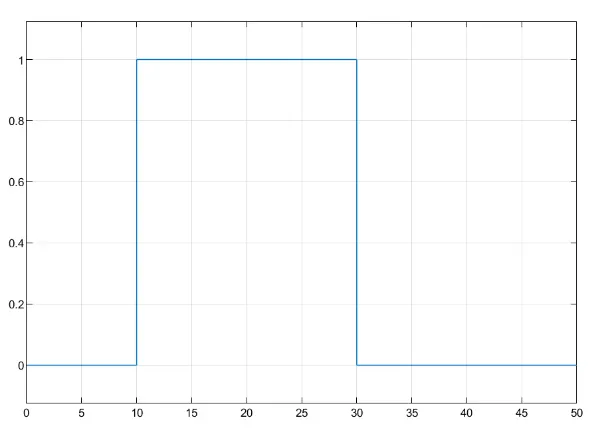
From the graph it is clear that the fan ON and OFF as per the temperature conditions.
CONCLUSION:
Both the objective completed successfully.