Week -2
SIMULINK MODEL FOR DOOR BELL AND THERMISTOR.
AIM-
1-To make a simulink model for a doorbell using a solenoid block.
2-To use thermistor to sense temperature of a heater and turn on/off the fan.
DOORBELL-
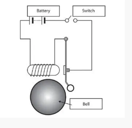
Making a simulink model of doorbell using solenoid block by using below parameters.
SIMULINK MODLE EXPLANATION-
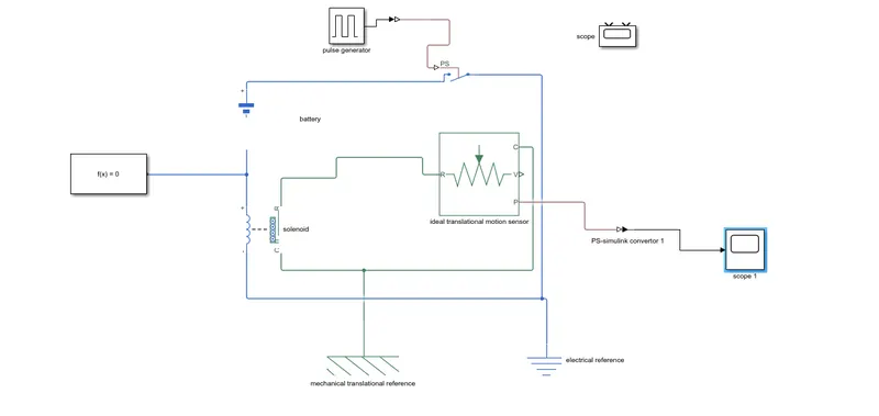
we have use the following blocks in the model.
- pulse generator
- switch
- battery
- solenoid
- ideal translational motor sensor
- mechanical translational reference
- electrical reference
- scope
as per conditions switch is closed for 2 seconds and then released.
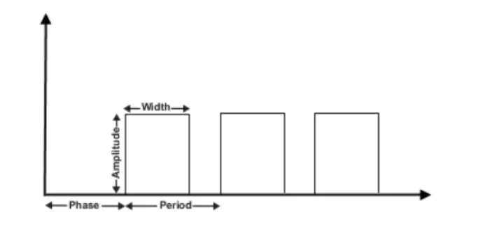
the pulse generator is used to create square wave pulse at regular intervals.the block wave form parameters,
amplitude,pulse width,period and phase delay,determine the shape of the waveform.
switch block is controlled by external physical signal and if the physical signal is greater than the switch ios closed
or else switch is open.
positive terminal os connected to block while as,the negative terminal is connected to the electrical reference .
when we conect solenoid block with the switch and battery we form a complete a electrical circuit.
the part C is connected with the mechanical reference. the ideal translational sensor is connected with the sloenoid block R
to observe the movement of the plunger.scope is connected with the ideal translational sensor to get the output.
The signal from the pulse generator was converted using the simulink PS converter and is given to the input switch.
a solenoid introduced and battery is connected to the it.the voltage of the battery connected was made as same as
that of the rated voltage of the solenoid.the switch is also connected to the same circuit.
The position of the solenoid plunger is measured using an ideal translational motion sensor connected to the circuit.
the initial position of this is set to 5mm in the tranaslational sensor. the scope is connected to visualize its behaviour.
the spring constant and damping parameters of the solenoid blockwas iltered to obtain the desired block.
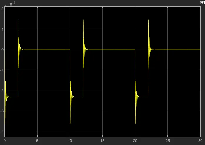
The simulation was run for 30 seconds and result obtained is shown below.it can be observed that at each 2seconds bell
was ringing.
BLOCK DIAGRAM:-
RESULT:-
CONCLUSION:-
giving input as the time period for 2seconds in the pulse generator to open and close the switch.when the switch is closed
the solenoid block receives electrical power from the battery and plunger moves from port R to port C to hit the bell and
produce sound.
Phtsical movement of the plunger is observed by using translational motion sensor and physical output is converted into
simulink output model is diplayed in the scope.by reducing the spring constant value and increasing the damping value
vibrations will be reduced.
THERMISTOR
Temperature source-20 from 0 to 10 seconds,
27 from 10 to 30 seconds,
23 from 30 to 50 seconds.
Fan conditions-ON if temperature above 25 degrees,OFF otherwis.
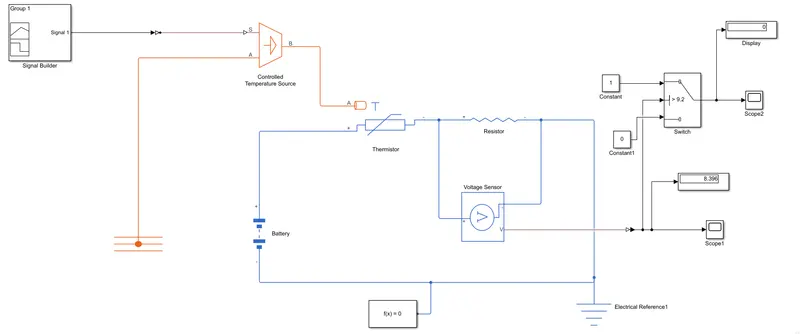
simulink model explanation:-
signal bolck is added to input the values as per given conditions.
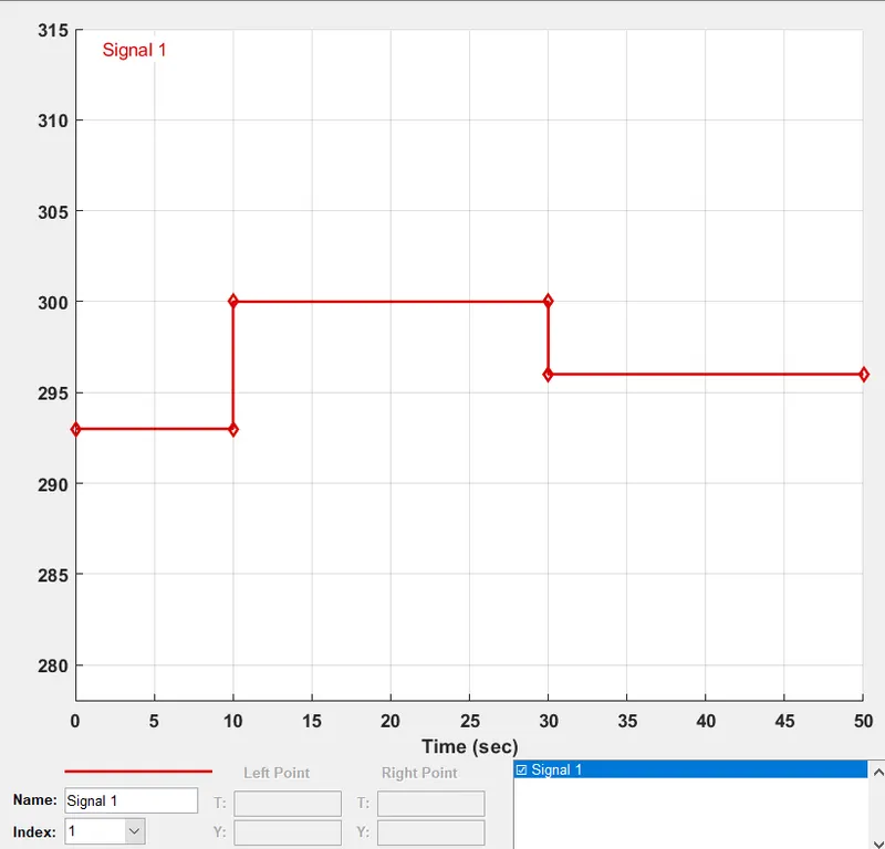
At point 1,time=0 sec to 10 sec and temperature=293k
At point 2,time=10 sec to 30 sec and temperature=300k
At point 3,time=30 sec to 50 sec and temperature=296k.
controlled temperature source represents an ideal source of thermal energy,that can be maintain controlled temperature
difference regardless of the heat flow rate.the difference is set by the physical signal port S.A positive diggerences causes
the temerature at port B greater than the temperature at port A.
thermistor is a type resistor whose resistence is based upon the temperature.
A linear resistor is used to control the amount of current from the battery.
the voltage sensor is used to convert the voltage measured between two points into physical signal voltage source
represents AC/DC.
electrical reference block is given:-
solver configuratrion:-each physical network represent by the connected simscape block requires solver
setting information for simulation.
WHAT IS THERMISTOR?
Thermistor is a device which measures temperatue,its working is based on the relationship between
resistance and temperature.here in simulink the thermistor block which is available is a positive temperature
co-efficient thermistor.so here resistance of thermistor increases or decreases with respect to temperature.
the output from the thermistor is actually in the form of voltage or current.the increase in voltage/current
indicates increase in temperature.
Detail temperature source:-
1-controlled temperature source-
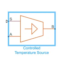
This block represents an ideal source of thermal energy that is powerful enough to maintain specified temperature different across source regardless of the heat flow consumed by the system.
2-Thermistor-
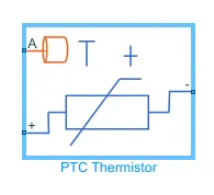
It is a type of resistor whose resistance depends upon temperature dependent on temperature,moe than in standard resistance .this thermistoe word is combination of thermal and resistor.
3-Resistor-
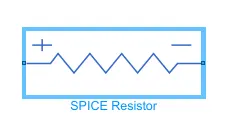
This is the linear resistor,described with then following equation.
v=I.R
where v=voltage
I=current
R=resistance.
4=voltage sensor-
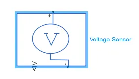
This device converts the voltage measured between two points of an electrical circuits into physical signal propprtional
5-electrical reference-
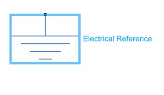
the ground must be connected to electrical reference port. A model with electrcial components must contain at
least one electrical refereance block.
6-switch-
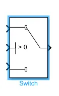
the switch block passes through the first input or the third input or based on the value of second input.the first and third
input are data inputs.the second input is control input.specify the condition under which the block passes the first input by
usong the criteria for passing first input and threshold parameters.
7-constant block-
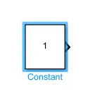
the constant block generates a real or complex constant signal value.use this block to provide a signal input.the block
scalar,vector,or matrix output.
8-ps-simulink converter-
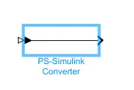
the ps-simulink converter block convert a physical signal into a simulink output signal.use this block to connect output
of physical network diagram to simulink scopes or other simulink blocks.
9-simulink ps- converter-
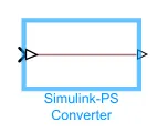
the block converts simulink into physical signal for operational use in model.
10-battery-
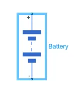
In battery positive termial is connected with switch and negative terminal is connected to electric reference.
11-solver configuration-
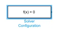
each physical network represent by a connected simscape block diagram requires solver setting information for simulation.
the solver configuration block specifies the solver parameters that our model needs before you can begin simulation.
12-scope-
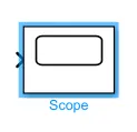
scope is connected with ideal translational motion sensor to get the ouput.the real time acquires data in chunks of size
numbers of samples from the real time application that is executing on the target computes.
SIMULATION BLOCK-
SIGNAL BUILDER BLOCK PARAMETERS:-
EXPLANATION:-
1-to create a simple fan model using thermistor,battery,voltmeter,a logical switch which are basic component of the
circuit we need in the simulink block.
2-first to represent a thermistor a "thermistor block" is taken an placed in a model.now to represent battery a "battery block"
is taken and the positive terminal of this block is connected to posoitive port of the thermistor.
3-now to represent a resistor a "resistor block" is taken from library browser and its positive port is connected to negative
port is cinnected to thermistor block.the negative port of the resistot block isconnected to negative of battery block.
now "electrical reference block" is cinnected near the negative terminal of the battery block.which represent the earthing of
real time circuit.
4-Now to represent a voltmeter a "voltage sensor"is connected parallel to the resistor block ,because to measure the voltage
across a component,voltmeter should always connected parallel to that component.
5-thus, we have completed our simple circuit model,but we need some physical quantities to as signal for thermistor to work.
6-In this case we need the fan to get ON and OFF at different temperatures.so to provide temperatuire ,we have used
"controlled temperature source block which will gives a specified temperature as output even though heat flow is more.
7-now to give different temperature to this "controlled temperature source" we need to send temperaturen signals.to send
these signals,we have a "signal builder block" which allows us to send any type of signal as inputs.
8-we have to double click on the "signal builder block" to set the signal configuration according to our requirement.
9-Above figure shows how signal are set in the "signal builder block".as this dialogue box opens,first we have to click on
"signal "at the top and then select "new" then select "custom"option.Now it will ask to give the value of y-axis and x-axis.
since we know that at which time we need temperature as mentioned in the starting.we can give those values in an array
in this box and then above signals are generated.
10-we can see in the figure that how different temperature given at dufferent times.so,thus we have created our signals
ankd before connecting it to the "controlled temperature source block"we have to convert these signals into physical value.
so to do this we have a "simulink ps-converter block".
11-so now the port B of controlled temperature source block is connected to port A of the thermistor block and port A of
controlled temperature source block is connected to the thermal reference block.in controlled temperature source block
a positive temperature difference causes the temperature at port B to be greater that the temperature at port A.
12-now the output of the "voltage sensor block"is connected to "scope block" first and before connecting to scope block
a "ps-simulink converter" is used to convert physical value to simulink values.
13-Now when we run the simulation and double click on thr "scope block" we will get the following graph.
14-from the above figure we can see that how voltage is changing with the change in temperature using this information
,we can set condition for fan to ON and OFF.
15-if we ibserve the graph ,we notice that from time 0 t 10sec when the temperature is 293k,voltage is between 0.0095
and 0.01 and from time 10 to 30 sec when the temperature is 300k,voltage is between 0.0125 and 0.013 and from time
30 to 50 sec when the temperature is 296k,voltage is nearly 0.011.
16-as mention in the objectives fan should be ON when the temperature is more than 25degree celcius i.e 298.15k ,from
the above graph when voltage is more than 0.011the fan should be ON and when volatge is below the 0.011 the fan
should get OFF.
17-this above logic is used to ON and OFF the fan.to do this we have used a switch block that routes the signal according
ti the condition provide.
18-the centre [port of switch block is connected to the ps-simulink converter whhich gives the voltage values.the top port
of the switch block is connected to a constant block of value 1 and thee bottom port of the switch block is connected to
another constant block of value 0.
19-the centre port of switch block is condition input which means that when the value from voltage source block is more
than threshold value in the switch block,then it will pass the value 1.which we have specified in top port of the switch block.
if the vlotage from the voltage sensor is less then the threshold value in the switch block then it will pass the value 0.which
we have specified in the bottom port of switch block.here it acts as a transistor in real time circuit.
20-to set the threshold value of the switch block we have to double click on the switch block and then we can change the
value of threshold.since we want to be ON only when the temperature is 300k so the threshold value is given as {0.011}.
so when the voltage is more than 0.011the switch will give the value 0 as which certainly means fan will get off.
21-Now the output of switch block is connected to another scope block to get results.
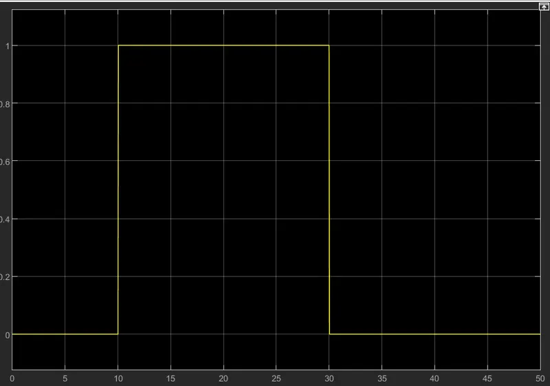
22-by double clicking the scope block we can observe the above graph.here we can clearly see that when temperature is 300k
the fan is ON and at remaining temperature the fan is OFF.
RESULT:-
CONCLUSION:-
1-thus,both the objective was achieved successfully.
2-similar approach can be used for simulating other physical device using simulink.
3-fan temperature was sensed by the thermistor in the heater model.
4-From 0-10 seconds fan is OFF because the temperature is 293k which is below 298k,after 10 seconds it goes to 300k,
so fan will turn ON because temperature exceeds 298k.after 30 seconds fan will turn OFF because temperarure goes
296k and less then 293k.