Week -2
1)
Aim: To make a Simulink model of doorbell using solenoid block with a situation where the switch is closed for 2 seconds and then released and also to observe the physical movement of the plunger.
Theory:-
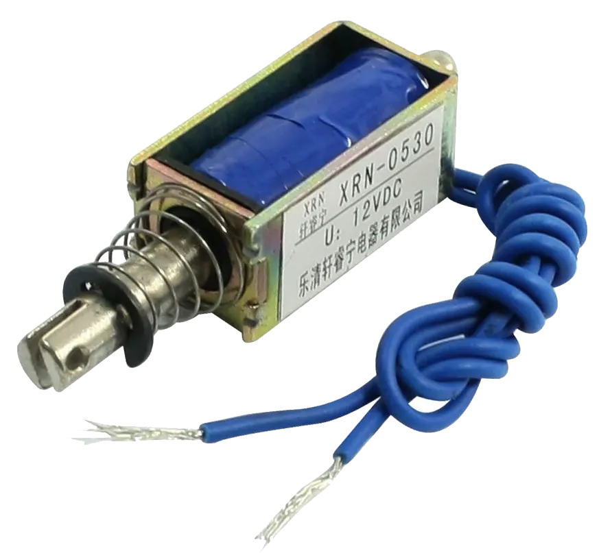
SOLENOID: A solenoid is a device comprised of a coil of wire, the housing and a moveable plunger (armature). When an electrical current is introduced, a magnetic field forms around the coil which draws the plunger in. More simply, a solenoid converts electrical energy into mechanical work.The coil is made of many turns of tightly wound copper wire. When an electrical current flows through this wire, a strong magnetic field/flux is created.
The housing, usually made of iron or steel, surrounds the coil concentrating the magnetic field generated by the coil. A solenoid is a device comprised of a coil of wire, housing and a moveable plunger (armature). When an electrical current is introduced, a magnetic field forms around the coil which draws the plunger in. More simply, a solenoid converts electrical energy into mechanical work. The plunger is attracted to the stop through the concentration of the magnetic field providing the mechanical force to do work.
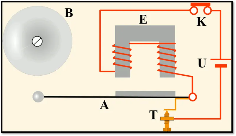
DOORBELL: The most widely used form is the interrupter bell, which is a mechanical bell that produces a continuous sound when current is applied. The bell (B), which is often in the shape of a cup or half-sphere, is struck by a spring-loaded arm (A) with a metal ball at the end called a clapper, actuated by a solenoid (E). In its rest position the clapper is held away from the bell a short distance by its springy arm. When the switch (K) is closed, an electric current pass from the battery (U) through the winding of the solenoid. It creates a magnetic field that attracts the iron arm of the clapper, pulling it over to give the bell a tap. This opens a pair of electric contact (T) attached to the clapper arm, interrupting the current to the solenoid. The magnetic field of the electromagnet collapses, and the clapper springs away from the bell. This closes the contacts again, allowing the current to flow to the solenoid again, so the magnet pulls the clapper over to strike the bell again. This cycle repeats rapidly, many times per second, resulting in a continuous ringing.
The tone of the sound generated depends on the shape and size of the bell resonator. Where several bells are installed together, they may be given distinctive rings by using different size or shapes of bell, even though the strike mechanisms are identical.
Another type, the single-stroke bell, has no interrupting contacts. The hammer strikes the gong once each time the circuit is closed. These are used to signal brief notifications, such as a shop door opening for a customer, rather than continuous warnings.
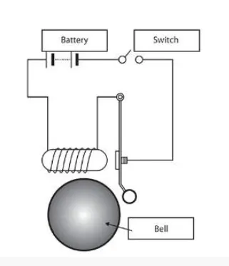
Governing Bell diagram given:
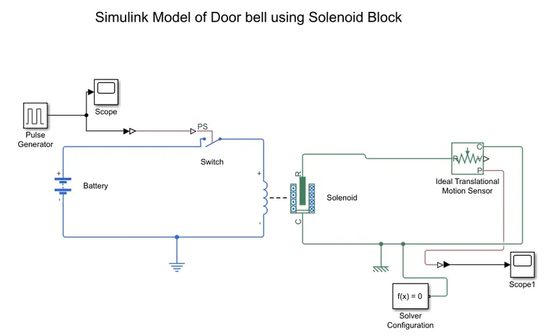
Simulink Model of Doorbell:
BLOCKS USED: -
- Pulse Generator: - The Pulse Generator block generates square wave pulses at regular intervals. The block waveform parameters, Amplitude, Pulse Width, Period, and Phase delay, determine the shape of the output waveform.
- Simulink-PS Converter: - The Simulink-PS Converter block converts the input Simulink signal into a physical signal. Use this block to connect Simulink sources or other Simulink blocks to the inputs of a Simscape physical network.
- Switch: - The Switch block models a switch controlled by an external physical signal. If the external physical signal PS is greater than the value specified in the Threshold parameter, then the switch is closed, otherwise the switch is open.
- Battery: - The Battery block implements a generic dynamic model that represents the most popular types of rechargeable batteries.
- Solenoid: - The Solenoid block represents the electrical characteristics and generated force for the solenoid
- Solver Configuration: - Each physical network represented by a connected Simscape block diagram requires solver settings information for simulation. The Solver Configuration block specifies the solver parameters that your model needs before you can begin simulation.
- Ideal Translation Motion Sensor: - The Ideal Translational Motion Sensor block represents a device that converts an across variable measured between two mechanical translational nodes into a control signal proportional to velocity or position.
- Scope: - Display signals generated during simulation.in simple word display graph with respect to time.
- Electrical and Mechanical Translational reference:- Both electrical and mechanical translational system should have one reference port.
LOGIC USED :-
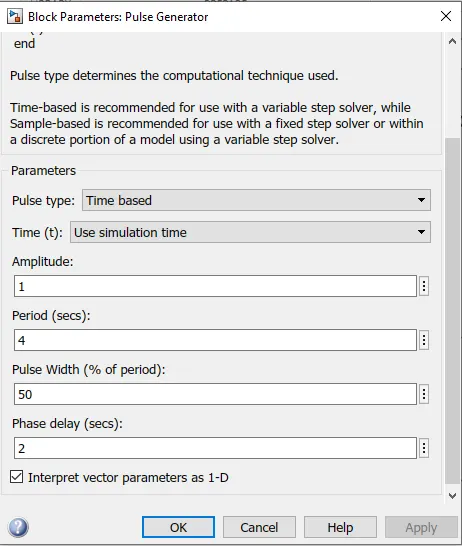
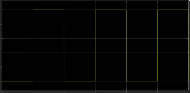
1. Firstly, the pulse generator is block is used to give signal inputs like amplitude, pulse width, period and phase delay to determine the shape of the output length. Scope is attached to it to see the graph of wavelength. I have assigned following vlues as shown in the figure below
The scope shows the input in form of waves
2. After that Simulink-PS Converter is used to convert signal input to physical system and send to the switch block.
3. To complete the circuit the battery, switch and solenoid block are used and connect to each other. The electric reference is used as a ground. All systems are connected in series. The solver configuration block is used to specify the solver parameter.
4. The mechanical part of solenoid (clapper) is connected with ideal translation motion sensor because the motion of clapper is translation and for ground the mechanical translation reference is used.
5. The scope is connected to an ideal translation motion sensor to see the output graph of plunger motion. The output is as follows,
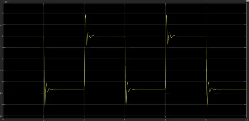
In the above graph we can see that the switch is closed for 2 sec after that switch is open. Amplitude is equal to 0 means the switch is closed. We can also see that the clapper strings every 2 seconds. The motion of clapper is as we can see I above graph with the help of scope.
We can get a smooth translational output if we increse rhe damping coeffiecient from currently 2 to 10 . below graph shows the output after increasing damping
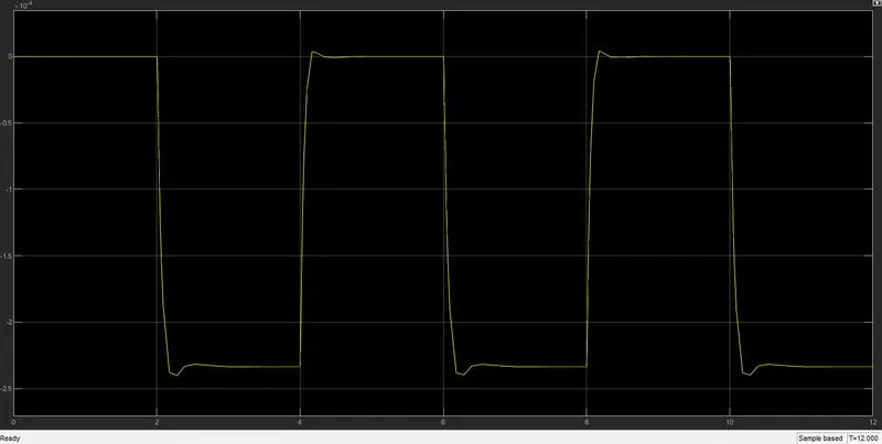
CONCLUSION: We can conclude from the above output results that we have successfully simulated doorbell mechanism operated by solenoid with less damping and by increasing the damping
**************************************************************************************************************************************
2. Aim :
To create a simulink model using a thermistor to sense the temperature of a heater & turn on or turn off the fan as per the below conditions:
Temperature source: 20 °C from 0 to 10 seconds, 27 °C from 10 to 30 seconds, 23 °C from 30 to 50 seconds. Fan conditions: ON if the temperature above 25 °C, OFF otherwise
Theory:
Thermistor: A thermistor is a thermally sensitive resistor that exhibits a precise and predictable change in resistance proportional to small changes in body temperature.How much its resistance will change is dependent upon its unique composition. Thermistors are part of a larger group of passive components. And unlike their active component counterparts, passive devices are incapable of providing power gain, or amplification to a circuit.
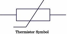
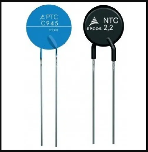
There are two types of thermistors. "NTC or Negative Temperature Coefficient thermistors", and "PTC or Positive Temperature Coefficient thermistors". The difference is that NTC thermistors exhibit a DECREASE in resistance as body temperature increases, while PTC thermistors exhibit an INCREASE in resistance as body temperature increases.
Given Inputs :
Input Temperatures:
T= 200 C which in kelvin is 273 K from 0 to 10 sec
T= 270 C which in kelvin is 300 K from 10 to 30 sec
T= 230 C which in kelvin is 297 K from 30 to 50 sec
Condition for fan operation
ON if T > 250 C which is 298 K
else OFF
Simulink Model :-
Blocks used:
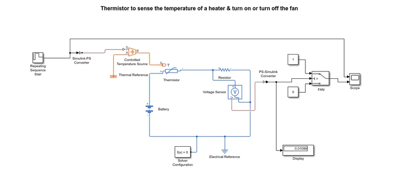
- Thermistor: This block represents an NTC thermistor using the B-parameter equation. The resistance at temperature T is given by R(T) = R0*exp(B*(1/T-1/T0)) where R0 is the Nominal resistance at the reference temperature T0, and B is the Characteristic temperature constant. The temperature T of the thermistor is governed by the equation m*c*dT/dt = Q where Q is the net heat flow into port A, m is the mass and c is the lumped specific heat capacity. The thermal mass m*c is calculated from the Thermal time constant t_c and the Dissipation factor K_d using the equation m*c = K_d*t_c.
- Resistor: The voltage-current (V-I) relationship for a linear resistor is V=I*R, where R is the constant resistance in ohms.
- Signal builder: To build the input Temperature signals
- Scope: Used for plotting input and output
- Simulink-PS converter: Converts the Simulink input signal to a Physical Signal.
- PS- Simulink converter : Converts the input Physical Signal to a Simulink output signal.
- Controlled Temperature source: This block represents an ideal energy source in a thermal network that can maintain a controlled temperature difference regardless of the heat flow rate. The temperature difference is set by the physical signal port S. A positive temperature difference causes the temperature at port B to be greater than the temperature at port A.
- Thermal reference: To grounding the thermal network
- Electrical reference: To grounding the electrical network
- Mechanical rotational reference: To ground the mechanical rotational parts
- Solver configuration: Defines solver settings to use for simulation for simscape models as it is not predefined like simulink.
- Battery: Acts as power source
- Voltage sensor: To sense the threshold voltage.
- Switch: condition switch to control based on threshold value.
- Constant: The Constant block generates a real or complex constant value signal. Use this block to provide a constant signal input.
- Display: The Display block shows the value of the output data. You can specify the frequency of the display. For numeric output data, you can also specify the format of display.
Logic used :
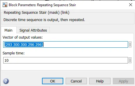
- We need to define the inputs required in repeating sequence stair block to provide the signal to thermistor through controlled temperature source. Simulink-PS converter is used to convert the signals to physical system. Below image shows we give the temperature input in form of arrays for every 10s i.e why sample time is kept at 10 wherein temperature sensor keeps the input temperature constant for every 10 seconds.
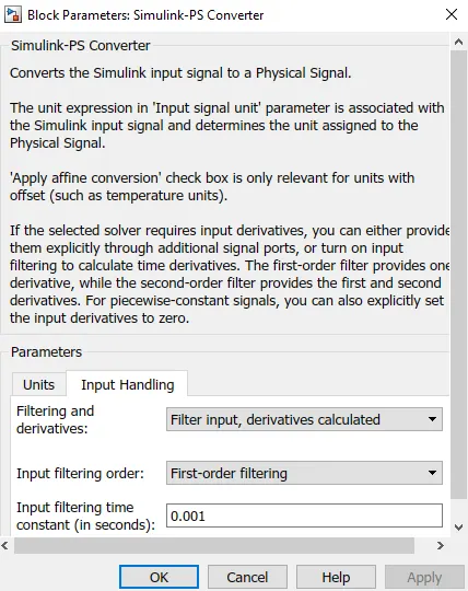
- The battery and voltage sensor are connected in series and resistor is connected in parallel to voltage sensor. The solver configuration is also used to specify the solver parameter. The electric reference is also used to ground the electric system.
- The voltage sensor is connected to switch to control the fan with the help of PS-Simulink converter to convert signal in Simulink input. After that we use scope to decide threshold value of switch. Also, we connected the display to show the last simulation value so we can decide our threshold value with the help of PS- Simulink converter.
- In the switch threshold value can be found. First we connect a constant block of 25 degree celsius i.e 298 K to get the threshold voltage for the switch i.e 0.01189.
- If the temperature is above the threshold limit, then it gave “1” as output which means fan switch on and if the temperature is below the threshold limit, then it gives “0” as output which means fan switch off.
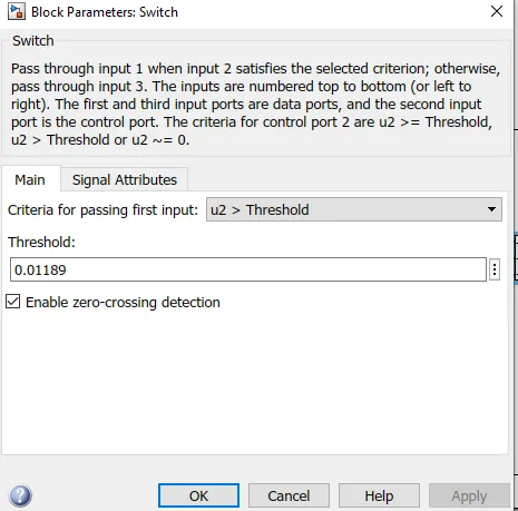
- At the end of system scope is connected to see output for fan on or off for different temperature inputs. We run the simulation for 50 sec because we take time limit in signal builder as 50 sec to get output
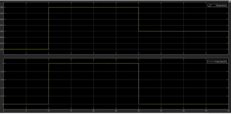
- In above graph we can saw form 0-10 sec signal is “0” because in this time the temperature was 20℃ or 293 K which is below 25℃ mean fan is switch off. After that from 10-30 sec signal is “1” because in this time the temperature was 27℃ or 300K which is above 25℃ means fan is switch on. At the end from 30-50 sec signal is “0” because in this time the temperature was 23℃ or 296k which is below 25℃ or 298K mean fans was switch off.
Conclusion : We can thus conclude that from the above output results of our Simulink model for solenoid operated heaters give correct output and satisfy with all input conditions.