Week -2
AIM:-
- To make a Simulink model of door bell using solenoid block.
- To make a Simulink model using a thermistor to sense the temperature of a heater and turn on or off the fan.
THEORY:-
SOLENOID:
- Solenoid are simple components that can be used for various applications. The name solenoid is derived from the Greek word “Solen” which means a channel or a pipe. Solenoids are used in both domestic and industrial equipments, they are available in various designs, each of them has their own specific applications.
- A solenoid is a long piece of wire which is wound in the shape of a coil. When the electric current passes through the coil it creates a relatively uniform magnetic field inside the coil.
- The solenoid can create a magnetic field from electric current and this magnetic field can be used to generate a linear motion with the help of a metal core. This simple device can be used as an electromagnet, as an inductor or as a miniature wireless receiving antenna in a circuit.
THERMISTOR:
- A thermistor is a resistance thermometer or a resistor whose resistance is dependent on temperature. The term is a combination of "thermal" and "resistor".
- There are two types of thermistors: Negative Temperature Coefficient (NTC) and Positive Temperature Coefficient (PTC). With an NTC thermistor, when the temperature increases, resistance decreases. Conversely, when the temperature decreases, resistance increases. This type of thermistor is used the most. A PTC thermistor works a little differently. When temperature increases, the resistance increases, and when temperature decreases, resistance decreases. This type of thermistor is generally used as a fuse.
GOVERNING DIAGRAM:-
DOOR BELL USING SOLENOID
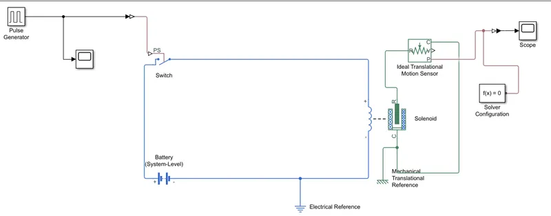
SIMULINK MODEL:-
1.DOOR BELL USING SOLENOID:
EXPLANATION:
- From the above governing circuit of a door bell, we know that we need a switch, solenoid, battery and a
plunger.
- So, in order to get all these components into a Simulink model we have to taken blocks that perform same
action what the above devices perform
- Now first a 'Solenoid Block is taken to represent a solenoid in the model, then to represent the battery we have
taken Battery Block from the library browser
- Then this 'Solenoid Block' and 'Battery Block' are connected to each other via positive and negative terminals.
- A Switch Block is placed in between 'Solenoid Block' and 'Battery Block and it is connected with both the blocks.
- Now for the Switch to operate we need to provide a physical signal through 'PS' port in the 'Switch Block. The provided physical signal should be greater than the threshold of the switch, for switch being closed, or else it will open.
- Now this whole battery, switch and solenoid path is connected to an Electrical Reference Block which represents earthing of the circuit. This Electrical Reference Block should be connected with negative port ofthe 'Battery Block'.
- Then in the Solenoid Block 'R' and 'C' are two variables which represent plunger and fixed point respectively.
- Now this 'R' is connected to a 'R' of 'Ideal Translation Motion Sensor Bock, which senses the position of the
plunger in the 'Solenoid Block and gives the output.
- Now in 'Ideal Translation Motion Sensor Bock the outputs are given as 'V' and 'P' which represent the velocity and position of the plunger. Since we are only interested in knowing the change in position of the plunger, so we need only results from P output.
- Now 'C in the 'Ideal Translation Motion Sensor Bock is a mechanical translation conserving port, which means
that the mechanical process starts from 'R' and ends at 'C' and again it starts at 'R' and the cycle goes on.
- So 'C' in the ideal Translation Motion Sensor Bock' is connected to a 'Mechanical Translation Reference which represents a fixed point where it is rigidly clamped in real time.
- Similarly 'C' of 'Solenoid Block' is also connected to the same 'Mechanical Translation Reference as fixed point for the Solenoid
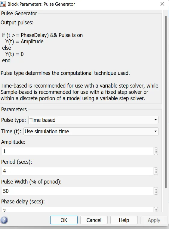
- From the above Figure we can observe that we have taken we have given period value as '4', pulse width as '50, phase delay as '2' and amplitude by default is 'T' we have not changed it. This means that initially the pulse will be zero, since we have given phase delay of '2' so till 2 sec the pulse will be zero and at 2 secs the pulse will start from zero to since we have given amplitude as 'I' and then now the pulse width will half of period so for the next two seconds the pulse will be at amplitude 'l' only, then it will again come down to zero at 4 second and then it will at zero for next 2 secs thus completing the period of 4 seconds.
- From starting to ending of the pulse it will take 4 secs of time period in which only for 2 secs the amplitude will be one and for rest of time it will be zero. So, after these 4 secs period again the pulse will be generated and thus cycle continues.
- To this 'Pulse Generator Block' a 'Scope Block' is connected to see how the pulse is generated.
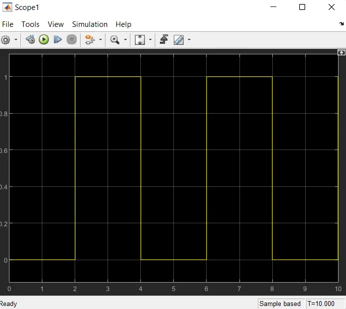
- The above figure is obtained by running the Simulink model and double clicking on the 'Scopel' block. This figure shows, how the pulse is generated and in this figure the X-axis represents the time and Y-axis represents the amplitude. As mentioned previously, the pulse has started after 2 seconds, then for next two seconds it has amplitude of 'l' and then next two seconds the pulse is again zero. The pulse is starting from 2 seconds and ending at 6 seconds which nothing but a time period of two seconds.
- Thus, this represents that when amplitude is one, the switch will be closed and when it is zero the switch will open. Since our objective is only to see the change in position of plunger when switch s closed for 2 secs so the we have the amplitude as I for 2 secs in the pulse generator by making the pulse width half of the period in the inputs for 'Pulse Generator Block'.
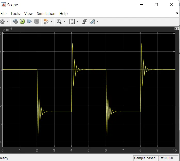
2.SIMULINK MODEL FOR FAN OPERATION USING THERMISTOR:
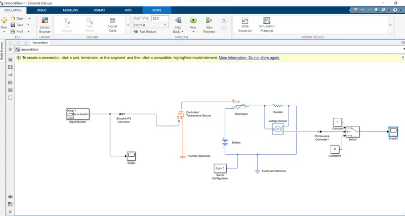
- Here the input is fed through the block Signal builder. The input data is given based on the initial conditions provided in the challenge
- Temperature source: 20 °C from 0 to 10 seconds, 27 °C from 10 to 30 seconds, 23 °C from 30 to 50 seconds
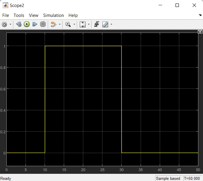
- Fan conditions: ON if the temperature above 25 °C, OFF otherwise
- As per the above-mentioned conditions, the input of the Signal builder is incorporated as shown Below.
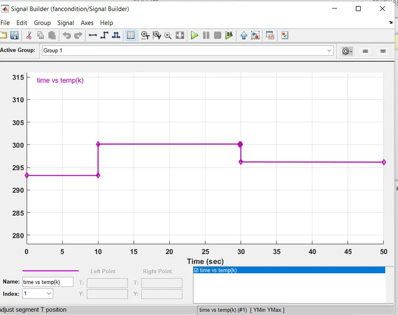
- Before this signal is been fed into the Controlled temperature source the settings of the Simulink Physical signal convertor" have to be modified. In the input handling, the filter input & derivative has to be selected instead of signals this is because here we use two heat source namely controlled temperature source (the ideal energy source in a thermal network that can maintain a controlled temperature difference regardless of the heat flow rate).
- The positive side of the thermistor is connected to the positive terminal of the battery and the negative side of the terminal is connected to the current sensor (which helps to detect the current flow in the circuit). This is followed by electrical resistance.
- The value from the current sensor is converted into the Simulink signal using the convertor. The value obtained is displayed in the display block. This just to give the threshold value inside the switch, which has 2 outputs based on 2 conditions if the value is above the threshold value of the output will be I and the value is below the threshold value of the output will be 0. The final output is recorded in the Scope.
CONCLUSIONS:
- Thus, both the door bell using solenoid and Using a thermistor to sense the temperature of a heater & turn on or turn off the fan as per the below conditions objectives were achieved successfully.
- Similar types of models can be used for simulating other physical devices using Simulink.