Week -2
Objective:
- To create a Simulink model of a doorbell using a solenoid, where the switch is closed for 2 seconds & then released.
- To use a thermister to sense the temperature of a heater & turn on the fan if the temperature is above 25° C.
Doorbell Mechanism:
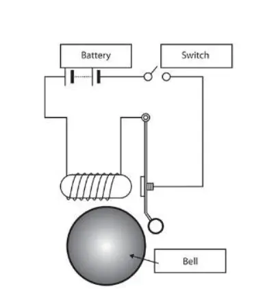
From the above images, we can depict that when the switch is turned on & the circuit forms a closed loop. Once the power supply passes through the circuit to the electromagnet, the plunger moves & rings the doorbell.
A solenoid is a type of electromagnet formed by a helical coil of wire whose length is substantially greater than its diameter, which generates a controlled magnetic field. The coil can produce a uniform magnetic field in a volume of space when an electric current is passed through it. This leads to the movement of the plunger insde the coil & acts a actuator, which converts a electrical energy to mechanical energy.
Simulink Model:
The input given to the pulse generator is as follows;
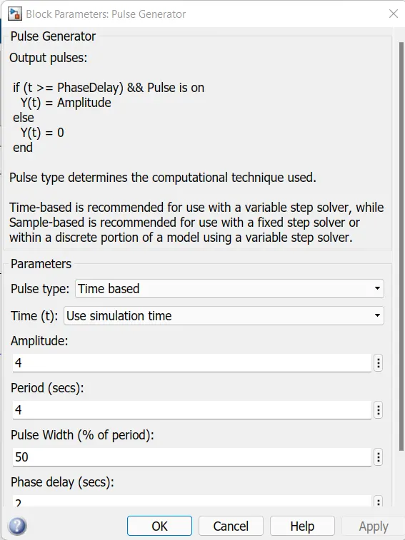
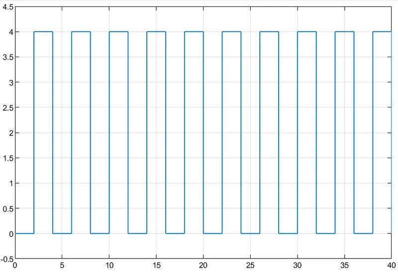
The amplitude is considered to be 4 sec & to achieve the 2 sec ring, the phase delay is considered to be 2 with pulse width being 50%.
The input scope of the system is as follows;
Explanation about the system:
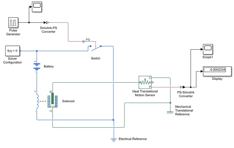
The input signal to the electrical system is given by the pulse generator which is connected to a switch, where a Simulink PS converter is used in between to convert the signal from simulink to physical state. In electrical system, one end of the switch is connected to a solenoid & other end to a battery, the circuit is closed by connected positive end of the solenoid to the negative end of the battery. Later, the plunger of a solenoid is connected to a Ideal Translational Motion Sensor, which senses the plunger movement & shows the distance in the display block with the graphical representation in the scope block. A PS Simulink converter is to be used to obtain the results in a simulink block. Also, Solver configuration & respective references need to be added to the system to obtain the desired output.
Output:
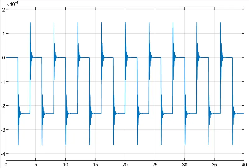
From the above output, we can observe that bell is ringing at the interval of 2 seconds with phase delay of 2 seconds.
Thermistor Mechanism:
A thermistor is a type of resistor whose resistance is strongly dependent on temperature, more so than in standard resistors. The word is a combination of thermal and resistor. Thermistors are widely used as inrush current limiters, temperature sensors (negative temperature coefficient or NTC type typically), self-resetting overcurrent protectors, and self-regulating heating elements (positive temperature coefficient or PTC type typically).
Depending on materials used, thermistors are classified into two types:
- With NTC thermistors, resistance decreases as temperature rises; usually due to an increase in conduction electrons bumped up by thermal agitation from the valence band. An NTC is commonly used as a temperature sensor, or in series with a circuit as an inrush current limiter.
- With PTC thermistors, resistance increases as temperature rises; usually due to increased thermal lattice agitations particularly those of impurities and imperfections. PTC thermistors are commonly installed in series with a circuit, and used to protect against overcurrent conditions, as resettable fuses.
Simulink Model:
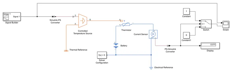
The input given to the signal builder with the provided data is as follows;
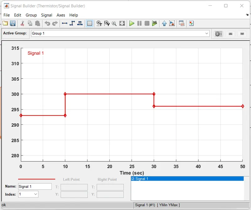
From the above input values, we can undertand the signal values for different time intervals.
Explanation about the system:
Initially, the condition temperature value needs to be considered as the input value, in order, to obtain the threshold value for the switch.
The input signal is produced by the signal builder with different temperature values at different time intervals. Next, the signal needs to converted to a physical state by using Simulink PS Converter, where the 'Filtering & derivatives' needs to be changed to 'Filter input, derivatives calculated' as the signal has more than 1 value. Then, the input signal is sent to the controlled thermal source, which is in turn connected to the thermistor.
In the electrical system, the thermistor is connected to a battery & a current sensor creating a closed loop. The current sensed value is first sent to the PS Simulink converter for conversion & later the value is displayed in display block with the graphical representation in the scope block. Before the values are shown in the graph, the values needs to go through a switch block to achieve the desired output(if temperature is more than 25°, the output value needs to be 1), where condition will be checked.
Finally, the system needs to be completed by connecting the solver configuration & the respective references to the respective system.
Output:
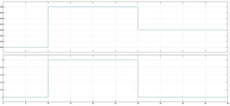
From the above graph, we can understand that the Fan is switched on when the temperature is above 25°,i.e, between 10 to 30 secs.