Week -2
DOORBELL:
Circuit Diagram
Process of the working of an electric bell
Now that you have an understanding of the important parts in an electric bell, the step-by-step process of the working of the electric bell is described below:
- The switch is pressed and current flows through the circuit.
- The electromagnet is powered and generates a magnetic field that attracts the iron strip towards it.
- The striker strikes the gong (bell).
- When the striking arm strikes the gong, the contact is broken and current stops flowing through the circuit.
- This causes the electromagnet to lose its magnetic field.
- The connected spring arm returns the striker to its original rest position.
- The contact is restored and current flows through the circuit (provided the main switch is still pressed).
- The process is repeated from the beginning.
SIMULINK BLOCK MODEL:
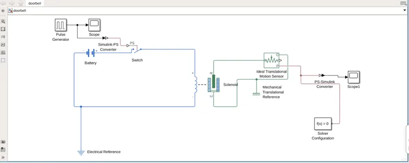
- The model consists of :
- Pulse Generator,to generate signal for opening and closing of the switch.The signal is converted to physical by simulink-PS converter.
- Battery,to supply power to the inducter.Switch,for opening & closing of circuit.
- Electrical reference,for grounding of the circuit.
- When the circuit is closed as per given signal the inducter induces emf and thus solenoid is activated.
- Thus ideal translation motion sensor senses it. The output physical signal is converted to simulink by converter.
- The output is plotted by the scope1.
PULSE INPUT:
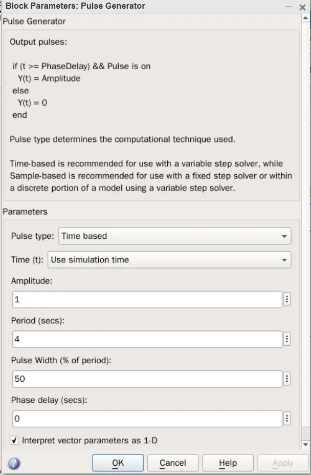
The input parameters applied as,
- Amplitude:1
- Period:4 secs
- Pulse Width:50(% of period)
- Phase delay(secs):0
PULSE OUTPUT:
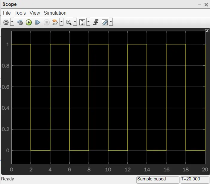
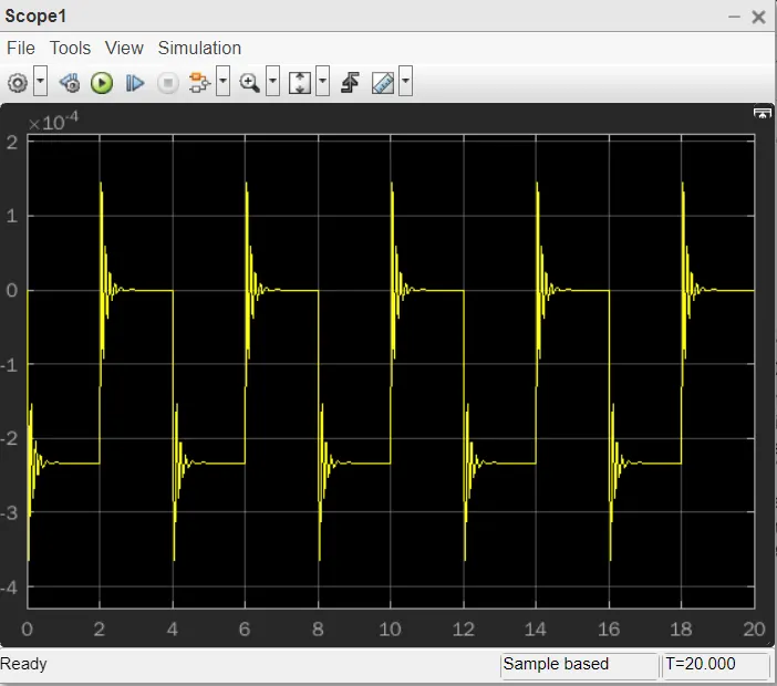
When the simulation is executed for time period of 20 seconds.we observed that the ring begins at 0sec and ends at 2secs for one interval.
At 0sec the buzz is maximum and is damped to zero at 2secs.
Thermistor: A thermistor is a resistance thermometer, or a resistor whose resistance is dependent on temperature.
Given condition:
2. Use a thermistor to sense the temperature of a heater & turn on or turn off the fan as per the below conditions:
Temperature source: 20 °C from 0 to 10 seconds, 27 °C from 10 to 30 seconds, 23 °C from 30 to 50 seconds
Fan conditions: ON if the temperature above 25 °C, OFF otherwise
BLOCK DIAGRAM:
EXPLAINATION:
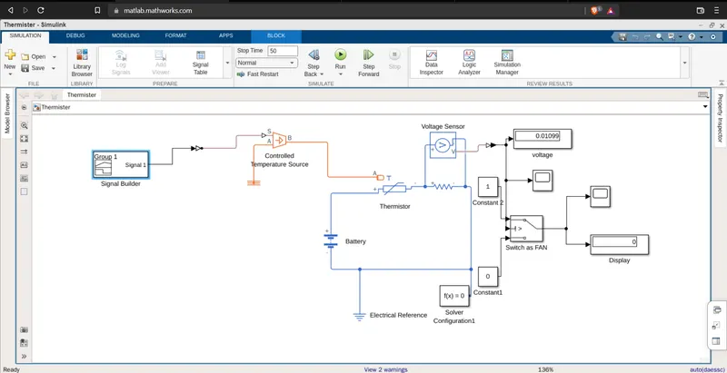
- Signal builder block,used to send the signals as per mentioned .
- The signal is sent to controlled temperature source by simulink to ps converter.
- Controlled temperature source,is used to provide a physical output based on the condition given to s port.And a port is connected to thermal reference which provide required initial condition to the connected thermal block of the solver.
- Thermistor is a device that changes its resistance as per temperature variation,here it senses the temprerature and varies the flow of current in the circuit by variating resistance.
- The change in current flow is also observed in the resistance in the circuit .These changes is sensed by voltage sensor.
- The output of voltage sensor is connected to the display via ps-simulink converter.Scope is connected to plot the variation in voltage which is sensed by voltage sensor.
- Switch,has 3 input ports the 2 port input controls output based on the threshold value.
- Here, the threshold value is set based on voltage output at given temperature(25°C )as constant block.The constants are applied to input ports1 & 3 and setted as 1&0 respectively.
- When the voltage is below thershold it is switched to constant '0' & when it is greater than threshold constant'1' is applied.Thus, switch acts as a FAN and operates as per temperature variation.
- The output of switch is displayed & it plotted by scope.
SIGNAL BUILDER :
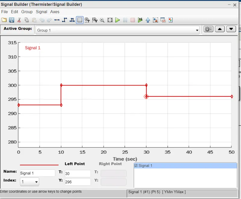
- Initially the axis are set and time is set for 50 seconds.
- Inputs:
- 20°C(293 K) from 0 to 10 seconds,
- 27 °C(300 K) from 10 to 30 seconds, FAN is ON
- 23 °C (296 K)from 30 to 50 seconds.
OUTPUT SCOPE OF FAN:
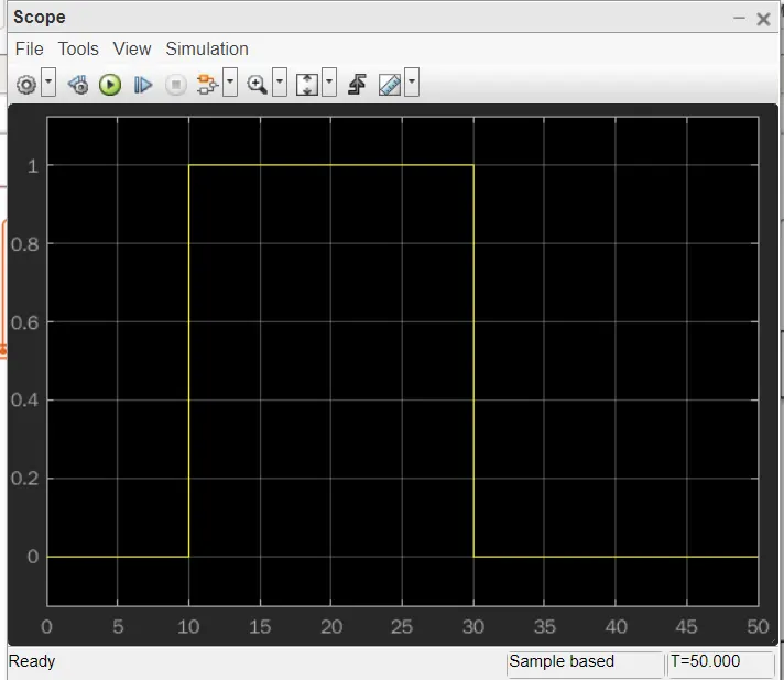
Thus, from the graph it is observable that from 0 to 10 seconds the fan is OFF as the Temperature is 20°C .The FAN get ON when temperature is 27°C between 10 to 30 secs.Later it is turned OFF as its temperature is 23°C .
Fan conditions: ON if the temperature above 25 °C, OFF otherwise
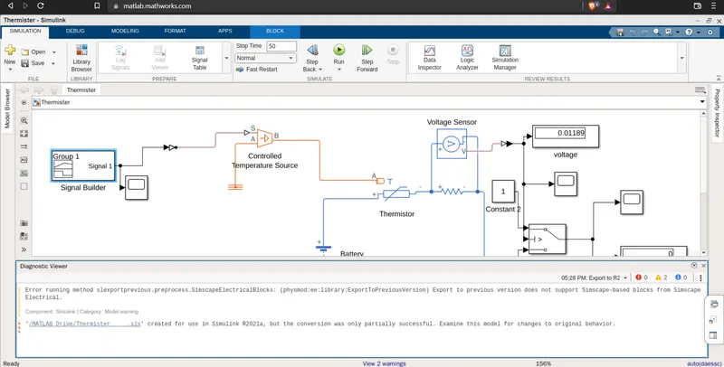
*DURING CONVERTION OF THE BLOCKS OF DOORBELL & THERMISTOR TO 2021A MATLAB FILE WE FOUND THE ERROR AS DISPLAYED,THUS IT WILL BE UPLOADED IN 2022a MATLAB .slx FILE.*FOR MORE EXPLAINATION PLEASE TO CONTACT.THANK YOU!!.