Week 2- 2R Robotic Arm Challenge
Aim: To write a MATLAB program to simulate the forward kinematics of a 2R Robotic Arm.
Description:
Kinematics is the analysis of motion without considering the forces.
A robotic arm is a type of mechanical arm that are programmed to execute a specific task or job quickly, efficiently, and extremely accurately. They are used in automobile, aviation and space industries.
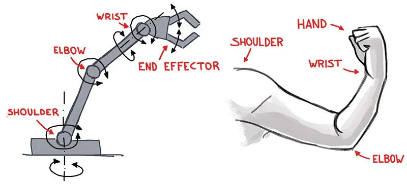
A typical industrial robot arm includes a series of joints, links and manipulators that work together to closely resemble the motion and functionality of a human arm.
The links of such a manipulator are connected by joints allowing either rotational motion or translational displacement. The links of the manipulator can be considered to form a kinematic chain. The end point of the kinematic chain of the manipulator is called the end effector.
A robotic joint provides relative motion between two links of the robot. Each joint provides a certain degree-of-freedom (DOF) of motion. In most cases, only one degree-of-freedom is associated with each joint.
Therefore, the robot's complexity can be classified according to the total number of degrees-of-freedom they possess.
Forward kinematics refers to the use of the kinematic equations of a robot to compute the position of the end-effector from specified values for the joint parameters.
The kinematics equations of the robot are used in robotics, computer games, and animation.
Using software like MATLAB, designers can simulate the range up to which the robot arm can be reached for a particular operation by inserting different size of robotic arm and different angles of robotic arm with reference surface.
In this program we will restrict the movement of the links in a 2D plane. We will take a simple Robotic arm with two links for our programming. We only need geometric properties such as length and degree of freedom of the manipulator bodies.
Here we have a 2R Robotic arm as shown in the figure:
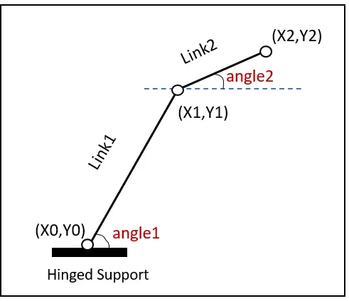
Link1 and Link2 are two links of the arm which makes angles θ1 & θ2 with the horizontal axis respectively.
The Link1 is attached to the base and end of Link1 is connected to Link2 and end of Link2 is connected to the end effector which performs the desired operation.
At the base the coordinates will be (x0, y0) = (0,0), at the end of Link1 and starting of Link2 the coordinates are (x1, x2) and finally at the manipulator the coordinates will be (x2, y2).
Here Link1 and Link2 are fixed and assigned as L1 (1m) & L2 (0.5 m). Multiple values of θ1 & θ2 are taken in the range from 0⁰ to 90⁰ and are assigned to Theta1 and Theta2 respectively.
So,
`x0=0 , y0=0` (At the Base)
`x1=x0+L1*cos(θ1)`
`y1=x0+L1*sin(θ1)`
`x2=x1+L2*cos(θ2)`
`y2=x1+L2*sin(θ2)`
The position for (x2, y2) has to be calculated for each value of Theta1 and Theta2. From different combinations of these values plots are created to finally make an animation.
Algorithm:
- Lengths of both the links are taken as input. Length of Link1 (L1) is taken as 1m and length of Link2 (L2) is taken as 0.5m.
- Base position of Link1 (x0,y0) is considered as origin (0,0).
- Angles traced by both the links for Link1 and for Link2 are taken as input by the ‘linspace’ command.
- To count the events in each loop a counter variable is assigned.
- Then two ‘for loops’ are used to iterate over the range of angles traced by both the links by using two counter variables.
- For each particular angle of Link1 and Link2, the end coordinates of Link1 and Link2 are calculated.
- Then for each particular position of Link1 and Link2, a plot is made which is then captured frame by frame to make a movie.
- A video file of '.avi' format is made to save the movie.
- The movie is then written into the video file and the final animation is thus created.
MATLAB Program:
% Forward Kinematics of 2R Robotic Arm
clear all
close all
clc

% Input

% Length of each link in m
L1 = 1;
L2 = 0.5;

% Origin Coordinates
x0 = 0;
y0 = 0;

% Angle traced by each link in degrees
Theta1 = linspace(0,90,15);
Theta2 = linspace(0,90,15);

% Counter value
ct = 1;

% Using for loop to plot the range of the arm
% i and j counter variables used to extract individual values from the
% arrays Theta1 and Theta2

for i=1:length(Theta1)

    for j=1:length(Theta2)

        % End Coordinates for Link1
        x1 = x0 + L1*cosd(Theta1(i));
        y1 = y0 + L1*sind(Theta1(i));

        % End coordiantes for link 2
        x2 = x1 + L2*cosd(Theta2(j));
        y2 = y1 + L2*sind(Theta2(j));

        % Plotting the robotic arm
        plot([x0 x1],[y0 y1],[x1 x2],[y1 y2],'linewidth',3)
        axis([-0.1 1.5 0 1.5])
        title('Kinematics of 2R Robotic Arm')
        pause(0.03)
        grid on

        % Capturing the current plot to merge later
        M(ct)=getframe(gcf);

        % Incrementing ct to capture the next frame in the next iteration
        ct = ct+1;

    end
end

% Making an animation from the collected frames
movie(M)

% Creating a videofile to save the animation
videofile = VideoWriter('Forward_Kinematics.avi','Uncompressed AVI');
open(videofile)

% Writing the animation in the file created
writeVideo(videofile,M)
close(videofile)
Errors Faced:
Output 1:
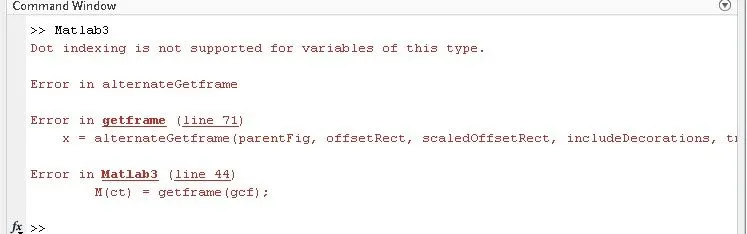
- ‘Dot indexing is not supported for variables of this type’ is an error given when brackets were given to 'for loop'. In MATLAB, for loop have no parenthesis.
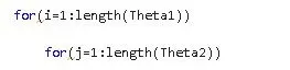
The brackets should be removed.
- Here even though the ‘getframe’ and below codes were correct, the codes above them were not written correctly.
In the plot code, the point and axis coordinates are incorrectly given:

By getting the coordinates wrong, the whole plot mapping was ruined and
the ‘getframe’ function could not capture and stitch together.
plot([x0 y0],[y0 y1],[x1 x2],[y1 y2],'linewidth',3) should be changed to
plot([x0 x1],[y0 y1],[x1 x2],[y1 y2],'linewidth',3) and
axis([-0.5 1.5 0 1.5]) should be changed to axis([-0.1 1.5 0 1.5]).
Output 2:

- Next error was in incorrectly calling the ‘videofile’ variable.

'writeVideo(vidoefile,M)' should be changed to 'writeVideo(videofile,M)'.
Result:
The output is obtained in form of an animated video clip. This animation can be viewed by visiting the link below.
Conclusion:
A simulation of the forward kinematics of a 2R Robotic Arm in 2D workspace was created using MATLAB program.
References:
https://uk.rs-online.com/web/generalDisplay.html?id=ideas-and-advice/robotic-arms-guide
https://www.sciencedirect.com/topics/engineering/forward-kinematics#:~:text=Forward%20kinematics%20refers%20to%20process,Cartesian%20coordinates%20of%20wrist%2Ffist.
https://en.wikipedia.org/wiki/Kinematics
https://en.wikipedia.org/wiki/Forward_kinematics
https://en.wikipedia.org/wiki/Robotic_arm
https://en.wikipedia.org/wiki/Degrees_of_freedom_(physics_and_chemistry)