Week 2- 2R Robotic Arm Challenge
SIMULATION OF FORWARD KINEMATICS OF 2R ROBOTIC ARM
OBJECTIVE:
To determine the motion of the robot arm with MATLAB & simulate the forward kinematics of 2R robotic arm to show its working environment in a video.
SOLUTION PROCEDURE:
Formula used in the forward kinematics of 2R Robot arm:
Length of the link1 & link 2 are assumed as L1 & L2 respectively & Angle of the link 1 & link 2 are assumed as Angle 1 & Angle 2 respectively.
Co-ordinates of the base of the robot is assumed as origin => (x0, y0) = (0,0)
Co-ordinates of the connector of the 2 links => (x1, y1)
x1 = L1 * cos (angle 1)
y1 = L1 * sin (angle 1)
Co-ordinates of the end effector => (x2, y2)
x2 = x1 + L2 * cos (angle 2)
y2 =y1 + L2 * sin (angle 2)
We have the below code structured in the following steps
- Inputs are assumed for the Length & angle of the links.
- Determination of the Co-ordinates of the connector and end connector for the entire angle range
- Plotting of the 2R Robotic arm with the co-ordinates for each condition.
- Saving all the image files created for each condition in one object
- Preparing the video file (avi) from that object using the write video command
CODE REFERENCE:
clear all
close all
clc
%INPUTS
%Length of the links
l1=1
l2=0.5
%Angle of the links with respect to the x axis
theta1=linspace(0,90,10)
theta2=linspace(0,90,10)
%Co-ordinates of the base(link1 starting point)
x0=0
y0=0
%Counter variable for tracking the images for each posistion
ct=1
for i = 1: length(theta1)
    THETA1=theta1(i)

    for j=1:length(theta2)
        THETA2=theta2(j)
        % Co-ordinates of link 1 & link 2 connecting point
        x1=x0+l1*cosd(THETA1)
        y1=y0+l1*sind(THETA1)
        % Co-ordinates of link 2 end or end effector/manipulator
        x2=x1+l2*cosd(THETA2)
        y2=y1+l2*sind(THETA2)


        %plotting
        plot([x0,x1],[y0 y1],[x1 x2],[y1 y2],'linewidth',3);
        axis([-0.1 1.5 0 1.5])
        %M variable to hold all the images together
        M(ct)=getframe(gcf);
        %counter increment to capture image of next posistion of the robot
        ct=ct+1
    end
end
%Video file creation
videofile=VideoWriter('Forward kinematics with MATLAB','Uncompressed AVI');
open(videofile)
writeVideo(videofile,M)
close(videofile)
RESULTS
We have the plots for each variation in the angles of the link 1 & Link 2. We have attached one sample image for reference.
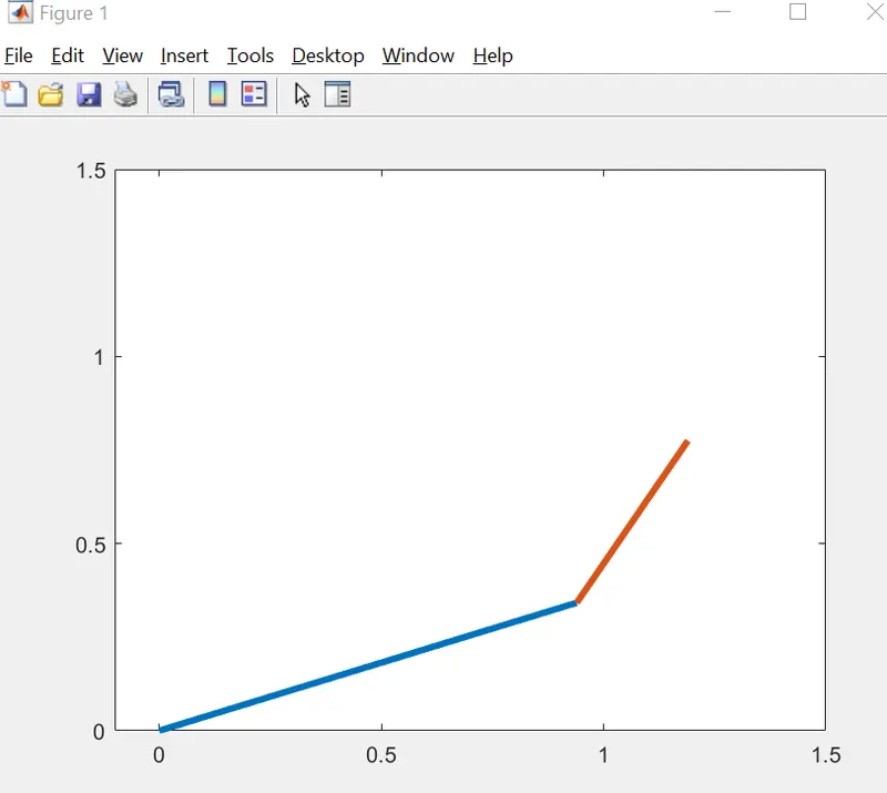
Kindly find the attached video file link which was converted from the above image.
Based on these, we are able to determine the working environment of the 2R robot arm with the specified input values and the position of the end effector position for each condition.