Week 2- 2R Robotic Arm Challenge
Aim: To stimulate the forward kinematics of a 2R (double-armed) Robotic arm using Matlab programming.
Theory:
The robotic arm stimulation is generally used in industrial workings, for lifting the products while they are on an escalator mover, to place the objects in an organized way, etc.
Here, we are going to calculate the workspace obtained by a robotic arm that has two links attached(Link-1 & Link-2). Imaginary robotic arm having two links is constructed with Picsart application as shown.
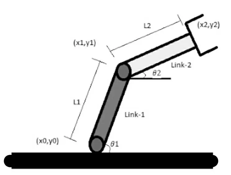
Figure representing the 2R robotic arm
By assuming the certain angles `theta1 and theta2`
and their lengths (x0,y0 - x1,y1) link-1 and (x1,y1 - x2,y2) link-2, we are going to stimulate the animation of the robotic arm's workspace.
Here are the co-ordinates of x and y at each point;
`x0 = 0` and `y0 = 0` (origin point)
`x1 = l*cosd(theta1)` and `y1 = l*sind(theta1)` (at mid point)
`x2 = x1 + l2*cosd(theta2)` and `y2 = y1 + l2*sind(theta2)` (end point)
Here, the origin point is at the start point where the arm is connected to the base.
the midpoint is at the endpoint of link-1 and the start point of link 2.
the endpoint is the one that handles the products, at the end of point 2.
Now, we are going to code the program and plot the 2R robotic arm using all the co-ordinates listed above;
CODE OF CO-ORDINATES;
clear all
close all
clc

%inputs
l1 = 1.5;
l2 = 1.0;

theta1 = 50;
theta2 = 30;

%co-ordinates
x0 = 0;
y0 = 0;

x1 = l1*cosd(theta1);
y1 = l1*sind(theta1);

x2 = x1 + l2*cosd(theta2);
y2 = y1 + l2*sind(theta2);

%plotting
line([x0,x1],[y0,y1],'linewidth',3,'color','b');
line([x1,x2],[y1,y2],'linewidth',3,'color','r');
Here, I assumed that Line-1 is 1.5 and Line-2 is 1.0, and `theta1=50` `theta2=30`
And the remaining co ordinate equations are equated, and the graph is plotted by executing it.
The graph;
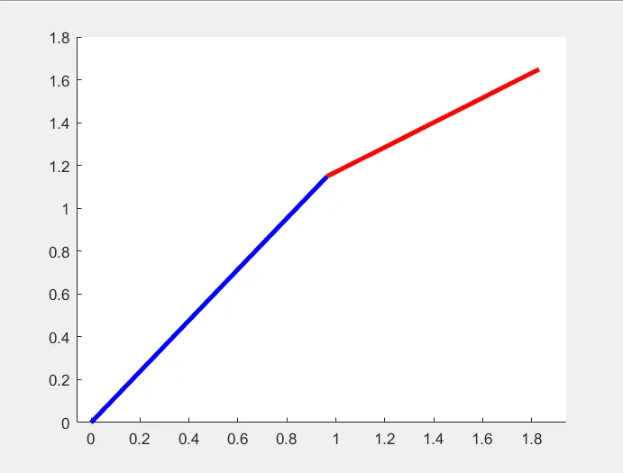
Therefore, The graph is plotted using the above program, Blueline represents line1 and Redline represents line2 angled at 50 degrees and 30 degrees.
but we can see that the graph is a stilled image, It is not animated. We need to get the graph in an animated form.
EXPLANATION FOR AN ANIMATED ROBOTIC ARM;
For that, we need to set the limitations of angles for both the line's in their workspace.
So, assuming the imaginary moments of theta1 and theta2 are below 90 degrees,
Creating 20 values for both the links up to 90 degrees.
As the link-2 is attched to link-1, for every 20 frames of motion of link-2, there will be a single frame motion of link-1. To get this work into execution, we need to use the linspace command to create the number of frames in between the total workspace. And the for loop inside the program conveys the information to be done in the animation.
CODE for ANIMATED GRAPH;
clear all
close all
clc

l1 = 1.5;
l2 = 1.0;

theta1 = linspace(0,90,20);
theta2 = linspace(0,90,20);

ct=1;
for i = 1:length(theta1)
    THETA1 = theta1(i);
   for j = 1:length(theta2)
    THETA2 = theta2(j);
    x0 = 0;
    y0 = 0;

    x1 = l1*cosd(THETA1);
    y1 = l1*sind(THETA1);

    x2 = x1 + l2*cosd(THETA2);
    y2 = y1 + l2*sind(THETA2);

    plot([x0,x1],[y0,y1],[x1,x2],[y1,y2],'linewidth',3)
    axis([ 0 3.0 0 3.0])
    pause(0.03)
    ct = ct+1;

  end
end
EXPLAINATION OF CODE;
1) For both theta1 and theta2, linspace command is used for creating set of frames for animation. (Here, i used 60 frames for both the links for better and smoother animation).
2) for loop is created for setting the repetition,
3) capitalized THETA is just a variable (it is nothing but a single frame at a position of `theta`
4) i and j values acts as indices for the `theta1 and theta2`
5) plot command is used for plotting the graph and linewidth is set to 3 for decent visibility.
6) Axis is set for the graph using axis command. positions for x and y can be adjusted according to the clear presentation.
7) pause function sets the travel speed of the arms. so here the minimum pause of 0.03 is choosen.
8) ct is set to impliment frame and so, ct = 1 and ct = ct+1. (represents each frame)
Finally, The 2R robotic arm is programmed to stimulate according to our commands. In this way generate a program for forward kinematics working.
And to get the programmed output as a film output for presentation purposes or inspecting the work for modifications to be done in programming,
we can also save the output or animated graph in an AVI format.
CREATING A MOVIE OF THE ANIMATED GRAPH;
For this, we need to a create an array called M which consists of 'ct'. and then create a new AVI(audio video interleave) file format.
creating a new video file using the videowriter command. In this command the file name and profile should be inserted.
we need to write the captured frames to this video file for working and we need to close the file.
CODE after inserting an array M and commands (getframe and videowriter) to the previous program for the generation of a video clip.
clear all
close all
clc

l1 = 1.5;
l2 = 1.0;

theta1 = linspace(0,90,20);
theta2 = linspace(0,90,20);

ct=1;
for i = 1:length(theta1)
    THETA1 = theta1(i);
   for j = 1:length(theta2)
    THETA2 = theta2(j);
    x0 = 0;
    y0 = 0;

    x1 = l1*cosd(THETA1);
    y1 = l1*sind(THETA1);

    x2 = x1 + l2*cosd(THETA2);
    y2 = y1 + l2*sind(THETA2);

    plot([x0,x1],[y0,y1],[x1,x2],[y1,y2],'linewidth',3)
    axis([ 0 3.0 0 3.0])
    pause(0.03)
    M(ct) = getframe(gcf);
    ct = ct+1;

  end
end

movie(M)
videofile = VideoWriter('forward_kinematics.avi','Uncompressed AVI');
open(videofile)
writeVideo(videofile,M)
close(videofile)
So, after inserting the certain commands like getframe and video writer, we also open the video file and coded it to get the frames and closed it.
now the AVI FILE will be exported. and the link for viewing it is provided below;
THE ANIMATED AVI(audio video interleave) FILE LINK IS HERE;
ERRORS OCCURED WHILE EXECUTING;
1) Observed that only a single arm is plotting while executing with two separate plots.
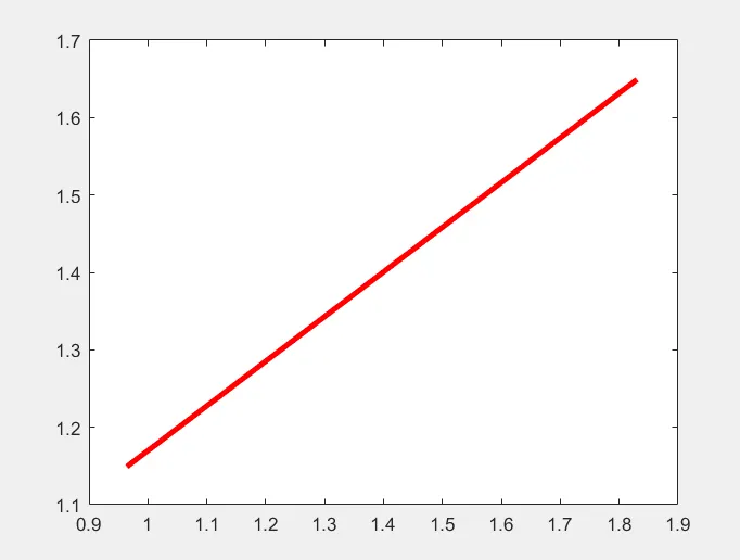
this is because when we execute with the plot command, only the recent plot will be projected. This issue can be solved by adding Hold on to the loop or program.
Anyways detailing all the coordinates in a single plot command can solve this issue even.
2) Got a minor parenthesis issue at the time of execution, the error line was mentioned by Matlab and got fixed it.
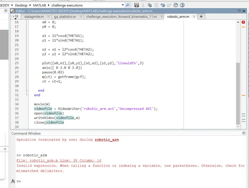
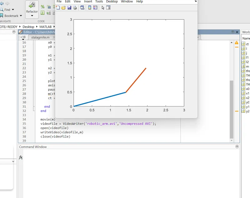
(fig-1) mentions error for parenthesis (fig-2) fixed and executed with 0 errors
Conclusion:
FInally stimulated the 2R robotic arm with 20 values for which,
Link 2 have 20 values for every value of Link 1, Whereas Link 1 has 20 values till the arm moment completion.