Week -2
AIM:
To make a Simulink model of doorbell using solenoid block and to make a Simulink model of a thermistor to sense the temperature of heater and turn on or turn off the fan as per the temperature conditions.
DOORBELL USING SOLENOID:
The Solenoid is a electromagnet. On passing current through the conducting wires a magnetic field is generated around it which attracts magnetic materials. This phenomenon is used in the bell. When the switch of the bell is pressed the current passes through the circuit, exciting the electromagnet and pulling the plunger towards the metal portion. This produces a ringing sound.
SIMULINK MODEL:
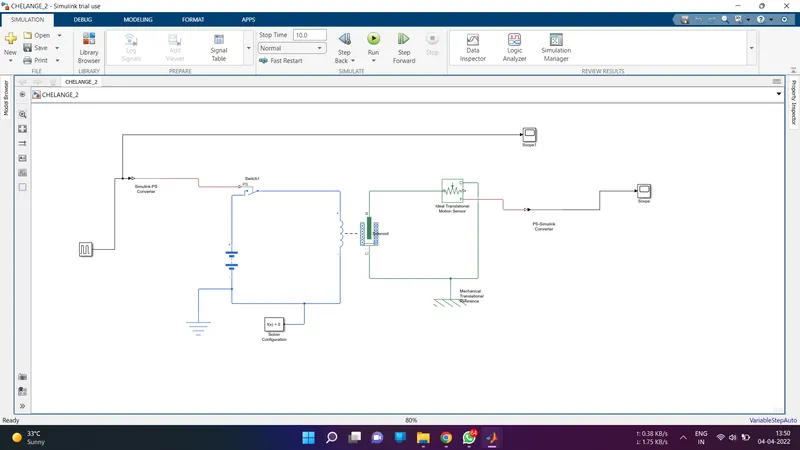
In the Simulink model I have used a pulse generator block as an input. The pulse is such that, every 2 seconds its ON.
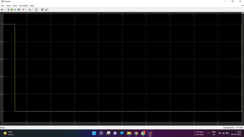
The above image shows the pulse pattern given as input. This cycle repeats for 20 seconds.
As we want the circuit to be close only in the interval of 2 seconds a switch block is used. The switch block has a threshold value of 0.8. The threshold of the pulse generator is 1. The switch will only close if the value of threshold is more than 0.8. This then connected to Solenoid block which contains the plunger arrangement. Initially when the plunger is away from C the value of X is 5 mm and when the plunger is near C the value of X is 0 mm. This can be seen from the output graph of plunger distance vs time. The position of the plunger is obtained by using the Ideal Translational Motion Sensor.
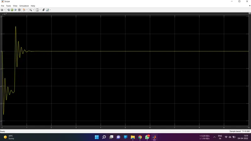
There are some spikes in the graph when switch is closed due to electromagnetic interferences.
FAN CONTROLLED BY THERMISTOR:
Thermistor is a sensor which is used to measure the temperature of the surrounding by comparing it with a known temperature and resistance values. The conditions are:
0-10 seconds 20 degree celsius
10-30 seconds 27 degree celsius
30-50 seconds 30 degree celsius
The input signal corresponding to the above parameters is given using a signal builder block.
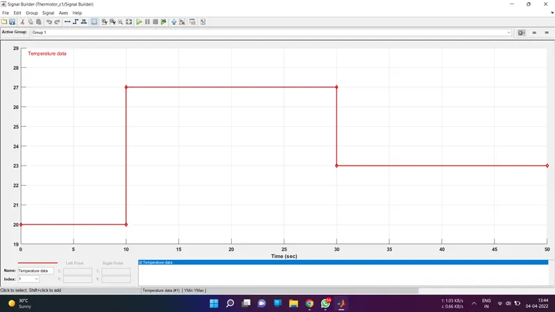
Signal Input
SIMULINK MODEL
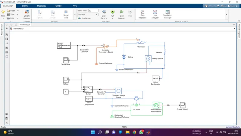
The requirement is such that, the fan should be turned on when the temperature sensed is greater than 25 degree celsius. To fullfill this objective we use a voltmeter to find the voltage of the circuit at different temperatures. It is found that, voltage at 25 degree celsius is approximately 0.23 V. Now, this voltage signal is passed through a switch. The switch is configured in such a way that, it is open if the voltage across the voltmeter is less than 0.23 V (temperature less than 25 degree celsius) and close if the voltage across the voltmeter is greater than 0.23 V (temperature more than 25 degree celsius). The threshold of the switch is set to 0.23 V.
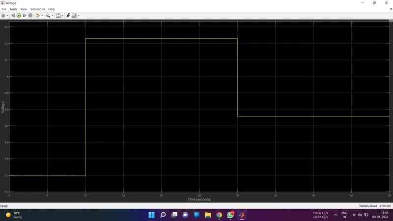
Output-
From the switch output we can see that, only output is between 10-30 seconds as the temperature is greater than 25 degree celsius. So, this output can be given to Fan for the simulation.