Week -2
PART-1
AIM:
Make a Simulink model of a Doorbell using a solenoid block.
OBJECTIVE:
- Designing a Simulink model of Doorbell.
- Create a situation where the switch is closed for 2 seconds and then released.
- Observe the physical movement of the plunger.
THEORY:
An electric bell is a mechanical or electronic bell that functions utilizing an electromagnet. When an electric current is applied, It actuates the solenoid in the hammer of the bell which pulls or pushes the metal core(hammer) striking against the bell, and thus it produces a clanging or ringing sound.
Working process of an electric bell.
- The switch is pressed, closing the circuit.
- The coil is energized and it pulls the plunger or striker
- The striker strikes the gong (bell).
- When the striker strikes the gong, the contact is broken and the circuit opens.
- This causes the electromagnet to release the plunger or striker closing the circuit again.
- The process is repeated from the beginning.
PROCEDURE/EXPLANATION:
- INPUT SOURCE
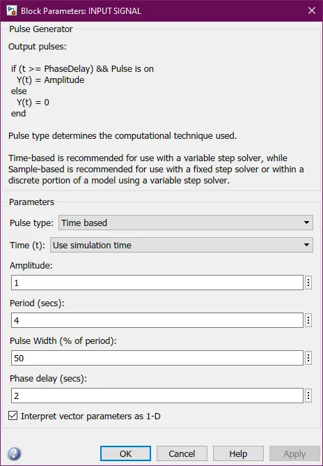
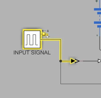
- The signal used to switch on and off the bell is generated through a pulse generator
- The pulse generator is set up to send a signal every 2 seconds so that the solenoid of the bell actuates every 2 seconds.
- As a single pulse includes 2 seconds on and 2 seconds off the period is taken as 4 seconds.
- Pulse width is taken as 2 seconds(1/2 of the period) hence 50%.
- a delay of 2 seconds is given as the pulse only needs to engage the switch after 2 seconds.
- The signal used to switch on and off the bell is generated through a pulse generator
- SOLENOID ACTUATED BELL
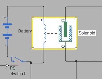
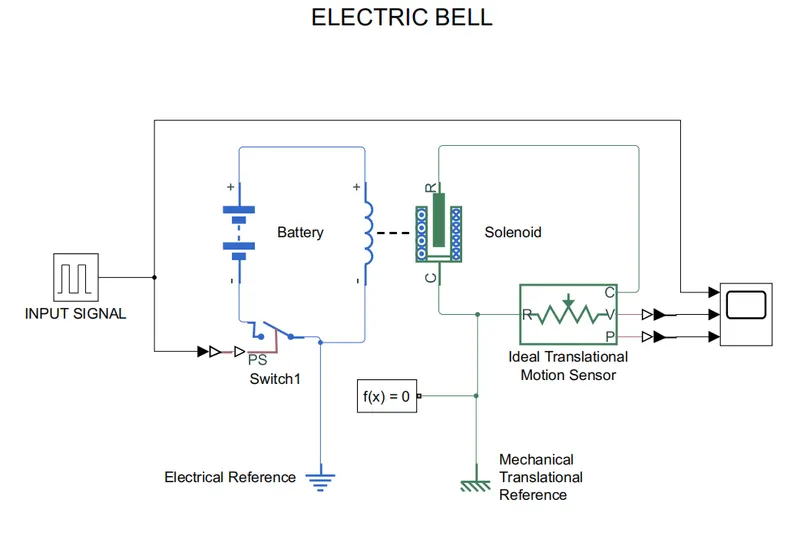
- The pulsing signal from the signal source is converted to a physical signal and used to switch on the circuit.
- When the circuit closes it actuates the solenoid.
- The actuation of the solenoid is considered as the actuation of the electromagnet in an electric bell.
- SOLENOID MOTION SENSOR
-
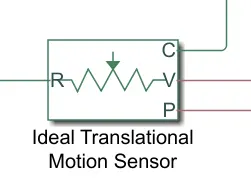
The solenoid is connected to a motion sensor that senses the velocity and position of the plunger.
-
The R and C port connects to the solenoid and reference respectively.
-
The motion sensor sends out physical signals of the plunger velocity(V) and plunger position(P) to a scope.
-
-
- SENSOR OUTPUT
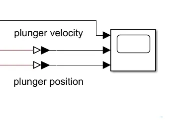
- The signals from the sensor are displayed on the scope to study the solenoid behavior.
- The scope displays the Input signals from the input source, the plunger velocity, and the position form the ideal translational motion sensor.
- SOLVER CONFIGURATION
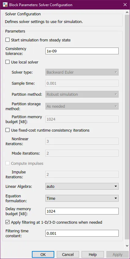
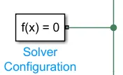
- At last, we provide a solver configuration. Because in the backend of the Simulink, there are many formulas undergoing calculations and we are using a simscape model in this design. Hence to give the required compilation of simscape blocks, we
need a solver. - For the solver in this Simulink simulation, the default configuration is utilized.
- At last, we provide a solver configuration. Because in the backend of the Simulink, there are many formulas undergoing calculations and we are using a simscape model in this design. Hence to give the required compilation of simscape blocks, we
SIMULINK MODEL:
SCOPE OUTPUT:
- INPUT SIGNAL
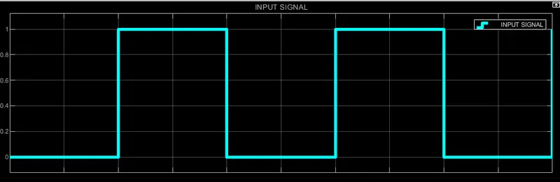
- The above graph shows the input pulse of width 2 seconds and delays 2 seconds.
- OUTPUT VELOCITY AND DISPLACEMENT OF THE PLUNGER
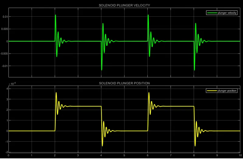
- There is noise in the plunger velocity and displacement as the dampening of the plunger is quite low.
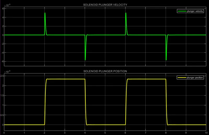
- Increasing the damping coefficient can reduce the noise.
- OUTPUT VELOCITY AND DISPLACEMENT OF THE PLUNGER WITH A DAMPING COEFFICIENT OF 6
GOOGLE DRIVE LINK: https://drive.google.com/drive/folders/1nxiMfMFSiD9gLSqXiaLKyP-2CxNCdr-h?usp=sharing
RESULT:
A Simulink model of an electric doorbell is built and the output is verified to check if it satisfies the given conditions.
PART-2
AIM:
Use a thermistor to sense the temperature of a heater & turn on or turn off a fan.
OBJECTIVE:
- Use a thermistor to sense the temperature of a heater & turn on or turn off the fan as per the conditions given:
-
20 °C from 0 to 10 seconds,
-
27 °C from 10 to 30 seconds,
-
23 °C from 30 to 50 seconds
-
- Fan conditions: ON if the temperature is above 25 °C, OFF otherwise
THEORY:
A thermistor is a type of resistor that has varying resistance depending on the temperature change, it is very sensitive to temperature changes and is used as a means to measure temperature.
thermistors act as a passive component in a circuit and are a popular choice of temperature sensing component in a circuit as it is robust, cheap, and accurate.
Uses of thermistor:
- Digital thermometer.
- Battery chargers.
- Automotive (engine, exhaust/inlet gas monitoring, etc).
- Air conditioners.
- Kitchen appliances, etc
The above mentioned are a few applications of a thermistor.
Working Principle of a thermistor-controlled appliance(Fan):
- The thermistor resistance is dependent on its temperature.
- We can measure the resistance of a thermistor using an ohmmeter or by measuring the voltage change at the output using a voltmeter.
- By measuring how the changes in the temperature will affect the resistance of the thermistor,and thereby the change in output voltage we can relate the thermistor’s resistance or the voltage at the output with respect to its temperature and connect a voltage controlled switch which will only close the circuit when the voltage across the input of the switch is above the set threshold(which in this case is voltage corresponding to 25-degree celsius).
- When the input voltage of the voltage-controlled switch goes above the threshold voltage (due to the change in resistance of the thermistor), the switch turns on the Fan, and when it goes below the threshold voltage it switches the fan off.
PROCEDURE/EXPLANATION:
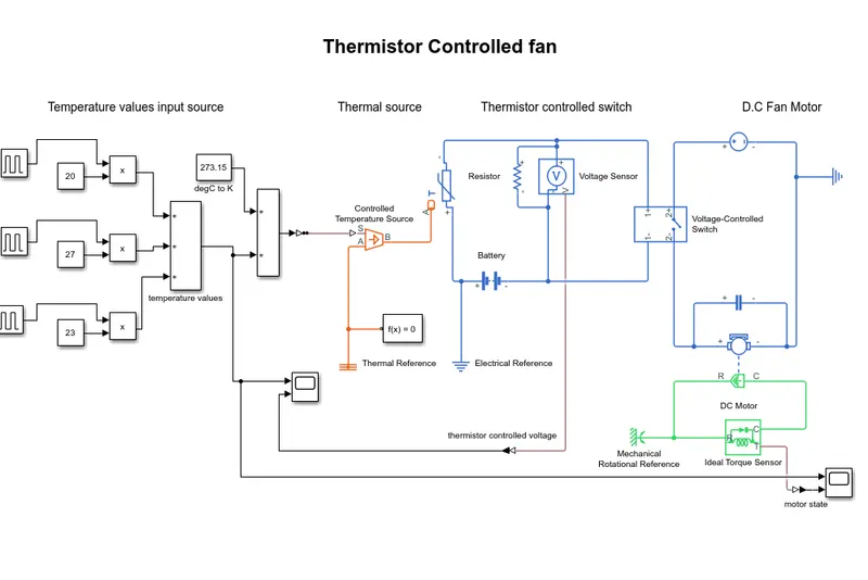
- Temperature values input source:
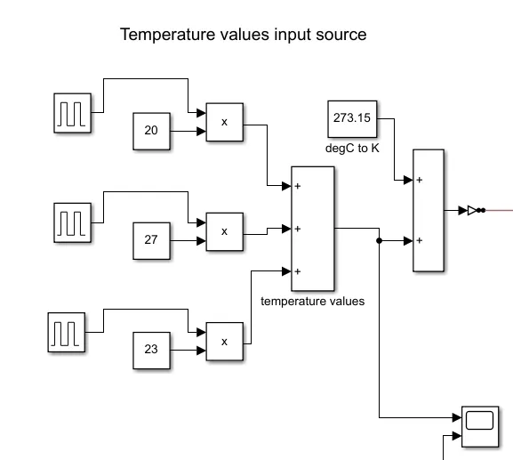
- The first part is the input source, where we use a signal builder to generate an input that is filtered.
- The following temperatures are used as an input with assigned durations:
- 20 °C from 0 to 10 seconds,
- 27 °C from 10 to 30 seconds,
- 23 °C from 30 to 50 seconds.
- The output of this subsystem is converted by a physical signal (PS) through a Simulink-PS converter. Along with that, a scope is also attached to examine the input.
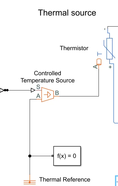
- Thermal source for the thermistor:
- A controlled temperature source is used to convert the filtered input as temperature values to the thermistor.
- the controlled temperature source is connected to a thermal reference and a solver configuration block as it is a necessity in Simulink to have a system connected to a reference to function properly.
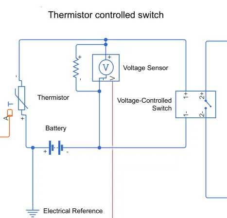
- Thermistor controlled switch to turn on and off the fan:
- The thermistor is connected to a circuit containing a voltage sensor, voltage-controlled switch, and a power source(battery).
- the voltage sensor is used to measure the voltage change due to the change in resistance of the thermistor as the temperature changes.
- the voltage is monitored using a scope to determine the input/threshold voltage of the voltage-controlled switch
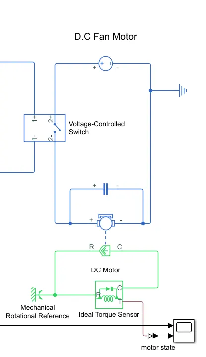
- D.C fan motor:
- The D.C fan motor is connected to a voltage-controlled switch, voltage source, a voltmeter, and an ideal torque sensor.
- The voltage-controlled switch is controlled by the thermistor, it would switch on or off the circuit based on the input received due to the thermistor.
- When The voltage-controlled switch is turned on it powers on the DC motor.
- An ideal torque sensor is connected to the motor to monitor the state of the Motor ie: if it is turning or not and the output is sent to a scope to be monitored.
 .
.
SIMULINK MODEL:
SCOPE OUTPUT:
- INPUT TEMPERATURE VS TIME VALUES AND THE THERMOCOUPLE CONTROLLED VOLTAGE OUTPUT:
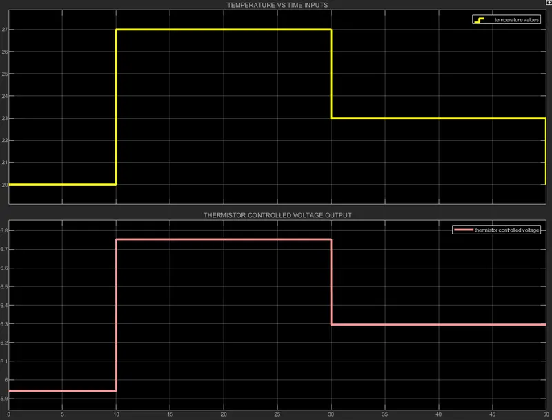
- The yellow plot shows the input signal generated by three sets of pulse generators with pulses of
- 20 degrees C for 10 seconds.
- 27 degrees C for 20 seconds.
- 23 degrees C for 20 seconds.
- The pink graph shows the variation of the voltage due to the resistance change in the thermistor being subjected to varying temperatures.
- INPUT TEMPERATURE AND D.C FAN MOTOR OUTPUT STATE
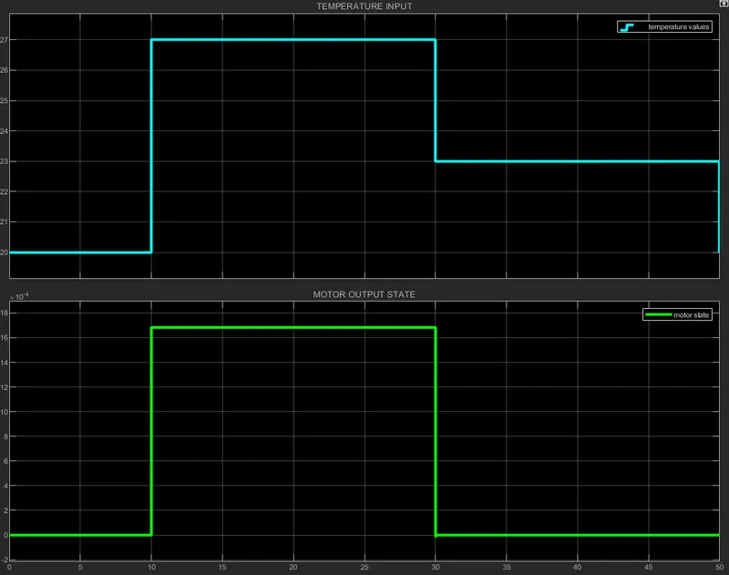
- The BLUE plot is the input temperatures:
- 20 degrees C for 10 seconds.
- 27 degrees C for 20 seconds.
- 23 degrees C for 20 seconds.
- The GREEN plot is the motor output torque across time for 50 seconds where:
- For the 1st 10 seconds, the torque is 0 as the switch is off
- For the next 20 seconds, the torque is non-zero as the switch is on and the temperature is above 25 degrees celsius as shown in the previous plot(yellow plot).
- For the last 20 seconds, the torque is zero the switch is off, as the temperature goes below the threshold temperature(25 degrees celsius).
GOOGLE DRIVE LINK: https://drive.google.com/drive/folders/17_HsF89p1acwVKVvtNAi3ZvEmMoIF1mA?usp=sharing
RESULT:
A thermistor-controlled heater fan is modeled using Simulink and the simulation output is verified.