Week -2
To model the simulation of a electronic bell we are to use various components of the simulink and simscape blocks. the blocks are from both electric and mechanical toolboxes. given below is the model construction of the door bell.
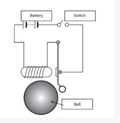
this diagram above gives the required logic for understanding of the working process of door bell. we are going to use the simulink blocks to try and simulate the above mechanism.
1.Simulink model of Doorbell:
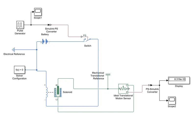
explanation:
we are create a model block which will make the bell ring in an interval of two seconds.
the first thing we require now is the way to feed the time for which the door bell rings, for which we are to use the pulse generator block from the simulink library.
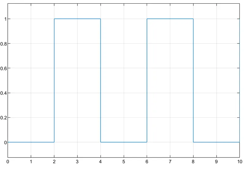
we are making its inputs in suck a way that the output should be a wave or an amplitude between every four seconds, which will help us generate bell ring time for every two seconds. output from the pulse generator is given below:
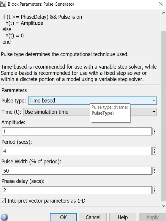
this is the input provided for the pulse generator to achieve uniform waves of equal intervals.
pulse generator output:
after then defining the pulse generator the pulse is made to effect the opening and closing of the switch for the ringing bell.
the switch is connected with a battery and a solenoid.
the solenoid converts the input current into mechanical energy. this is then connected to the motion sensor in order to know the output of the mechanical working system.
the scope and display blocks are used to understand the output of the main blocks and the reference points are made according to the nature of the system for better stability of the system.
the output scope or the representation of the working of intervals of the ringing bell is given below:
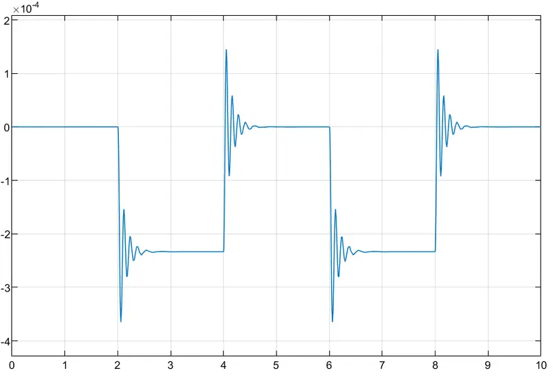
from the abouve over all output we can see that there is an uniform disturbance in the wave with an interval of two seconds. this disturbance is but the ringing of the door bell.
................................................................................................................................................................................................................................................................................................................................................................
2.Use a thermistor to sense the temperature of a heater & turn on or turn off the fan as per the below conditions:
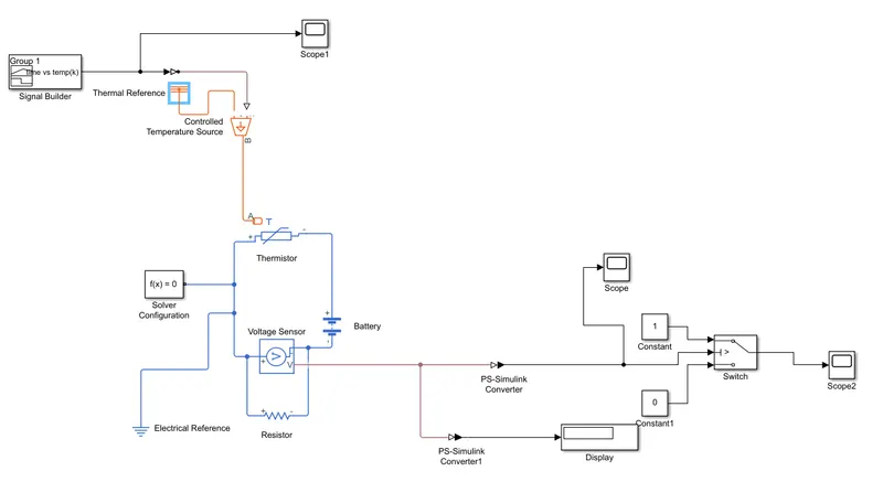
explanation:
we are to make a fan work for the varing temperature for varying time.
in this model we first make the varing temperature for varying time with the help of signal builder block.
the signal builder block is very much helpful in achieving the varing signal or anything that varies with respect to change in time.
we are making a time vs temperature plot or signal in which the temperature is made to change with respect to time.
the system is taken in kelvin temperature as its output is good readable in sim to ps input.
the change in temperature is given as 20 °C from 0 to 10 seconds, 27 °C from 10 to 30 seconds, 23 °C from 30 to 50 seconds. for which the fan should act un such way that ON if the temperature above 25 °C, OFF otherwise.
the temperature in degree celsius is made into kelvin and ploted with respect to time
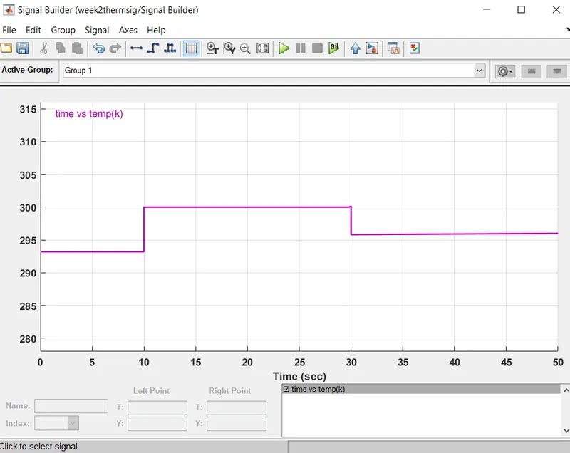
the signals from the signal builder is then converted to physical signal and made to enter controled temperature source, where the temperature is given as we made in signal builder block.
then it reaches the thermistor where it check the input heat or temperature.
the thermistor is connected to a battery and a voltage sensor an a small resistor.
the voltage sensor monitors the change in current from battery due to change in temperature.
the output monitored reading form voltage sensor is taken to a switch where it opens or closes according to the fluctuations in the voltage sensor.
the switch is given two conditions that is 1 and 0.
if the voltage is above certain value then one condition(ON), if not then the other(OFF).
the voltage sensor output is:
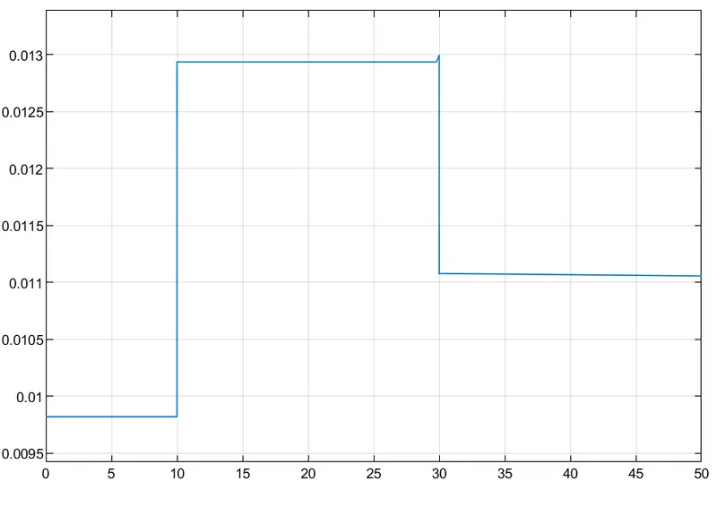
this is then fed into the switch with few conditions and the switch output is:
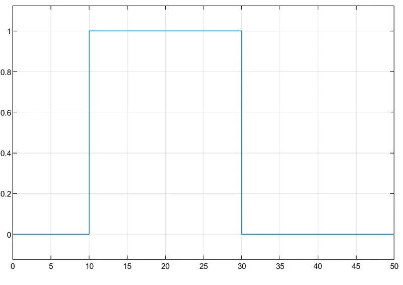
the switch varies from 1 and 0 due to the change in voltage sensor.
this 1 and 0 are the switch on and off of the fan.
errors faced:
few errors appeared when the reference block and the solver condition is not connected, later changed when blocks are made stable with connections.
conclusion:
the doorbell and the temperature controlled fan block model is created and the outputs are satisfying.