Week -2
Aim :- 1) To make a simulink model of Doorbell using solenoid block.
2) To make a simulink model to use a thermistor to sense the temperature of a heater & turn on or turn off the fan.
Theory :-
A) Solenoid :
A solenoid is a device comprised of a coil of wire the housing and a moveable plunger (armature). When an electrical current is introduced a magnetic field forms around the coil which draws the plunger in. More simply a solenoid converts electrical energy into mechanical work.
- The coil is made of many turns of tightly wound copper wire. When an electrical current flows through this wire a strong magnetic field/flux is created.
- The housing usually made of iron or steel, surrounds the coil concentrating the magnetic field generated by the coil.
- The plunger is attracted to the stop through the concentration of the magnetic field providing the mechanical force to do work.
1) To make a simulink model of Doorbell using solenoid block with the following details,
a) In the above arrangement, when the switch is closed the electromagnet receives electrical power from the battery and pulls the metal arm to hit the bell producing sound.
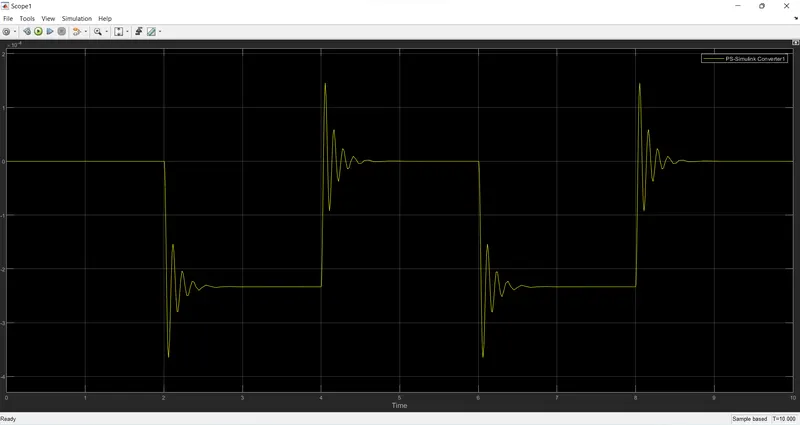
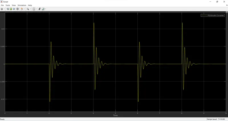
b) Create a situation where the switch is closed for 2 seconds and then released. Observe the physical movement of the plunger.
c) Assume remaining parameters.
Block Diagram :-
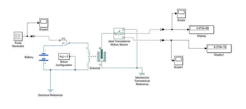
Explanation :-
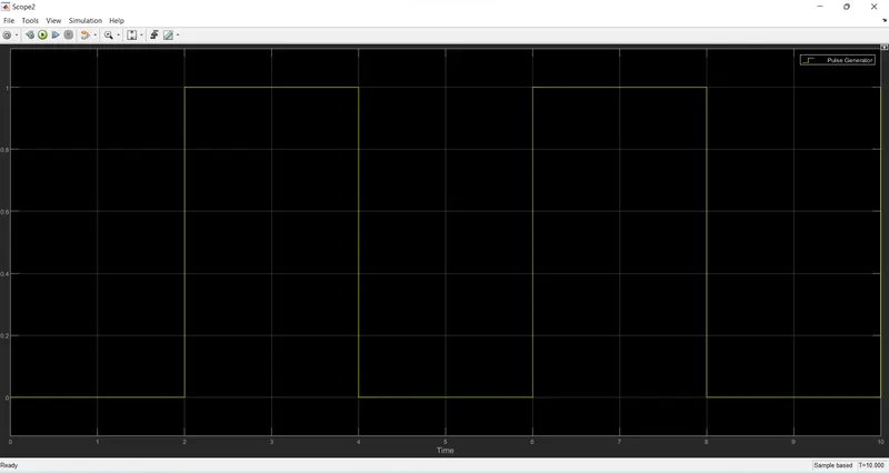
- An input signal is given through pulse generator according to given conditions.(Amplitude = 1, Period = 4 sec, Pulse width = 50%, Phase delay = 2 sec).
- A simulink-PS converter is used to convert the input simulink signal into a physical signal.
- A s/w is connceted to battery & solenoid respectively as shown in block diagram. In these, if the external physical signal PS is greater than the threshold then the s/w is closed, otherwise the s/w is open.
- Soleniod converts electrical signals to mechanical signals.
- The Ideal mechanical translational motion sensor convert an across variable measured between two mechanical translational nodes into a control signal proportional to velocity or position.
- A PS-Simulink converter is used to convert the physical signal into a simulink output signal.
- The solver configuration block specifies the solver parameters that, the model needs before we cna begin the simulation.
- The mechanical translation reference is used to represents a reference point or frame for all mechanical translational ports.
- The electrical reference block represents an electrical ground.
- In end, the scope & display blocks are used to obtain the output plot.
Input
Graph of Pulse Generator vs Time :
Output
a) Graph of Position vs Time :
b) Graph of Velocity vs Time :
B) Thermistor :
A thermistor is a type of resistor whose resistance is strongly dependent on temperature. The word is a combination of thermal and resistor. Thermistors are widely used as inrush current limiters, temperature sensors , self-resetting overcurrent protectors, and self-regulating heating elements. An operational temperature range of a thermistor is dependent on the probe type and is typically between −100 deg.C to 300 deg.C .
There are two types of thermistors, NTC & PTC thermistors
a) NTC Thermistors
- NTC stands for Negative Temperature Coefficient.
- In NTC thermistor, resistance decreases as its temperature increases.
- NTC thermistors are made using oxides of nickel, cobalt, copper, manganese & other materials.
- They are mainly employed for temperature control & measurement application.
- NTC thermistors are used for temperature range from -55 deg.C to 200 deg.C .
b) PTC Thermistors
- PTC stands for Positive Temperature Coefficient.
- In PTC thermistor, resistance increases as its temperature increases.
- PTC thermistors are made using barium titanate.
- They are used to protect electronic circuits from high temperatures.
- PTC thermistors are used for temperature range from 0 deg.C to 200 deg.C .
2) To make a simulink model to use a thermistor to sense the temperature of a heater & turn on or turn off the fan as per the below conditions,
a) Temperature source: 20 deg.C from 0 to 10 seconds, 27 deg.C from 10 to 30 seconds, 23 deg.C from 30 to 50 seconds.
b) Fan conditions: ON if the temperature above 25 deg.C, OFF otherwise.
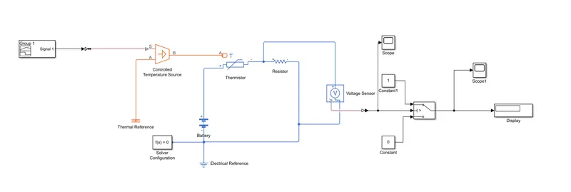
Block Diagram :-
Explanation :-
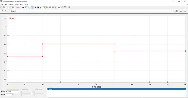
- Varying temperature over a time is given in the signal builder block.
- For 0 to 10 sec signal is set at 293.15 K; for 10 to 30 sec signal is set at 300.15 K & for 30 to 50 sec signal is set at 296.13 K.
- Here, the signal is a temperature, to take that as a temperature we are using Controlled Temperature Source Block.
- Controlled temperature source block is connected to thermistor.
- A resistor is connected in series with the thermistor block.
- Voltage sensor is connected to calculate the voltage across resistor.
- The electrical reference, thermal reference & solver configuration is also used in block diagram.
- We provide battery as a power source. And the switch block is used to satisfy the given condition for fan switch ON or OFF.
- To check the tershold voltage we use 298.15 K (25 deg.) as temperature in seprate or by removing the signal builder to the cricuit.(For these we have to remove Switch Block).
- The result which we get through these is used as tershold voltage value for our condition.
- Using two contant block, in which, i/p the value as '1' if condition is matched & '0' if condition is not matched.
- By using scope blcok, we can see the final result if fan is switched ON or OFF.
Input
Signal Builder Graph :
Output
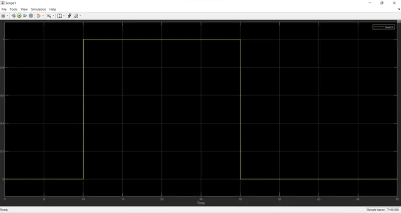
The graph for 50 sec time period is show above, we can see between 0 to 10 seconds the temperature is below 298.15 k (25 deg), as a result it does not have the voltage, between 10 to 30 seconds the temperature is above 298.15 K (25 deg.) there is an output as the voltage is beyond treshold point & for next 30 to 50 seconds the again the temperature is below 298.15 K (25 deg.), it does not have the voltage.