Week -2
Aim : Create a Simulink Model for a Doorbell using the solenoid blocks
Objective : creating a model of Doorbell in simulink model and study the arm the given inputs parameters
Theory : The definition of a solenoid is coil of wire that acts like a magnet when a flow of electricity passes through it. An example of a solenoid is the part of a car's starting system that transfers the electric current from the ignition to the motor 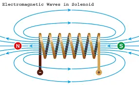
simulink block diagram for Door bell
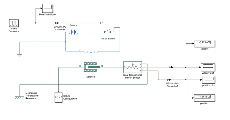
BLock used
Battery block
A battery block consists of multiple li-ion battery-cells, which are assembled in serial (the total voltage increases) and in parallel (the total capacity increases). Battery blocks have no protection mechanism against deep discharge and/or overcharge, and can be used as building/assembling components.
Pulse generator
A pulse generator is either an electronic circuit or a piece of electronic test equipment used to generate rectangular pulses
switch
switch switch_expression , case case_expression , end evaluates an expression and chooses to execute one of several groups of statements. Each choice is a case. The switch block tests each case until one of the case expressions is true
Ideal Translation motion sensor
The Ideal Translational Motion Sensor block represents a device that converts an across variable measured between two mechanical translational nodes into a control signal proportional to velocity or position. You can specify the initial position (offset) as a block parameter.
Scope
Scope blocks and Floating Scope blocks both display simulation results, but they differ in how you attach signals and save data.
Step Involved creating the model
- created a file named "door bell " save the folder
- first and most we need to insert the "solenoid block "
- In order to we pluse generator wwhich helps in creating the reqquired inputs condition
- an electrical reference is connected to negativ eterminal of the eelectrical circuit
- an ideal translation motion sensor is inserted into the model and input terminal is connected to output terminal of the mechanical side of solenoid block
- Reference terminal of solenoid and motion sensor is connected to mechanical reference and a solver configuration is connected to same reference
- a scope dissplay the output of the simulation in the form of plot or graph
Result
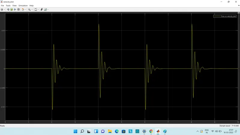
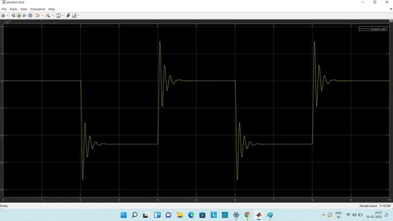
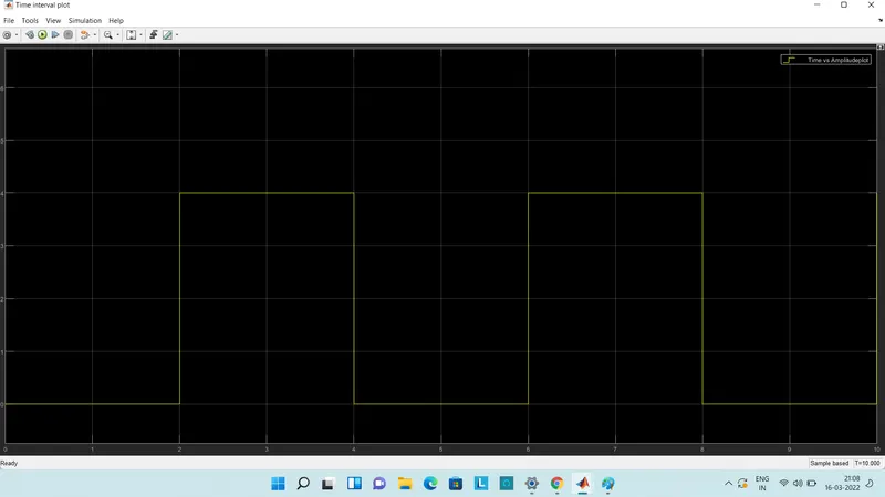
conclusion :
we created the door bell is completed by using the simulink and we generated required output as shown above graph
Part :2
Aim : To create simulink model for the sense temperature of heater turn when it temperature is above 25 c and off otherwise
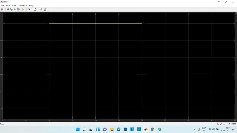
Objective : Temperature source 20 `degree`C from 0 to 20 seconds ,27 `degree` C 10 to 30 seconds,23 `degree`C from 30 to 50 seconds AFan condition above 25 `degree`C,Off otherwise
Theory :
The Thermistor is a solid state temperature sensing device which acts a bit like an electrical resistor but is temperature sensitive. Thermistors can be used to produce an analogue output voltage with variations in ambient temperature and as such can be referred to as a transducer. This is because it creates a change in its electrical properties due to an external and physical change in heat.
The thermistor is basically a two-terminal solid state thermally sensitive transducer constructed using sensitive semiconductor based metal oxides with metallised or sintered connecting leads formed into a ceramic disc or bead.
This allows the thermistor to change its resistive value in proportion to small changes in ambient temperature. In other words, as its temperature changes, so too does its resistance and as such its name, “Thermistor” is a combination of the words THERM-ally sensitive res-ISTOR.
Thermistors are available in a whole range of types, materials and sizes characterised by their response time and operating temperature. Also, hermetically sealed thermistors eliminate errors in resistance readings due to moisture penetration while still offering high operating temperatures and a compact size. The three most common types are: Bead thermistors, Disk thermistors, and Glass encapsulated thermistors.
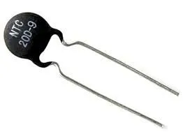
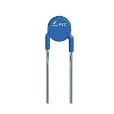
These heat-dependent resistors can operate in one of two ways, either by increasing or decreasing their resistive value with changes in temperature. Then there are two types of thermistors available: negative temperature coefficient (NTC) of resistance and positive temperature coefficient (PTC) of resistance.
Simulink Model
Block used
controlled Temperature source :The Controlled Temperature Source block represents an ideal source of thermal energy that is powerful enough to maintain specified temperature difference across the source regardless of the heat flow consumed by the system
voltage sensor
The Voltage Sensor block represents an ideal voltage sensor, that is, a device that converts voltage measured between two points of an electrical circuit into a physical signal proportional to the voltage
solver configuration
The Solver Configuration block specifies the solver parameters that your model needs before you can begin simulation.RE
Rpeating sequence
The Repeating Sequence block outputs a periodic scalar signal having a waveform that you specify using the Time values and Output values parameters. The Time values parameter specifies a vector of output times. The Output values parameter specifies a vector of signal amplitudes at the corresponding output times.
Explation model
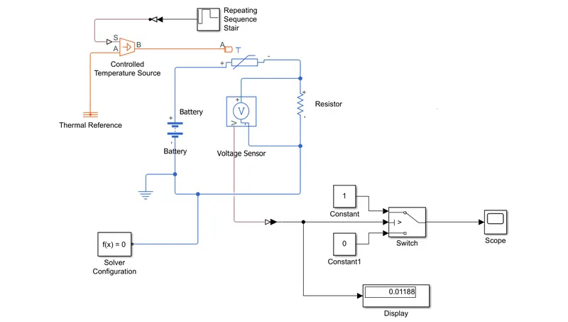
The above model shows the thermistor is used to sense the temperature and switch used start and stop
- firstly we need to add thermistor block ,port is connected temperature source block other end to thermal reference
- The temperature difference is set pyhsical signal port which connected to repeating source with help of PS converter
- repeating sequence stair is given as input to the theristor a controlled temperatur e source the definition ao repeating sequence strair block
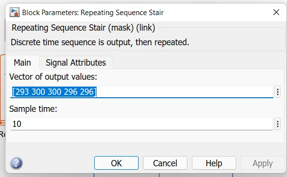
- the condition of the temperatur esource is definition inside the above window the sample time was taken as 10 sec and the simulink time was ytaken as 50sec
- Battery and resistor is connector in the thermistor circuits ,voltage sensor was given across this resistor to meaasure the voltage change during different temperature inputs
- The thresold temperature was given as 25 C and corresponding voltage is found out through a display connected to the voltage sensor at the time repeating sequence stair was given only the value is 25C or 298k
- At end of system scope is connected to see output for fan on (or) off .we run the simulation for 50 sec because we take time limit in repeating sequence stair hence we get the output
Result :
Conclusion:
we can conclude tha from the above output result of simulink model for operated heater for turn on /off.