Week -2
Simulink model of doorbell by using solenoid block
Aim :
We are to create a Simulink model of doorbell by using solenoid block.
Objective :
To create a model of doorbell by using solenoid block in Simulink.
To get the result scope we have to arrange the additional blocks that helps to get the output scope.
Theory :
A chime doorbell uses a specialized sort of electromagnet called a solenoid. A solenoid is just an electromagnet where the coiled wire surrounds a metal piston. The piston contains magnetically conductive metal, so it can be moved backward or forward by the electromagnetic field. The common chime design uses a solenoid to hit two tone bars in sequence.
The heart of a doorbell is an electromagnet. When you press a doorbell button, you complete an electrical circuit that allows household electricity to flow through the doorbell's internal electromagnet. The magnetic field generated by the electromagnet is then used to power a mechanism that creates the doorbell sound.
Required blocks :
Pulse generator,
Simulink-PS converter,
Switch,
Battery,
Solver configuration,
Electrical reference,
Solenoid,
Mechanical translational reference,
Ideal translational motion sensor,
PS-Simulink converter,
Scope,
Scope 1.
Simulink block representation of doorbell :
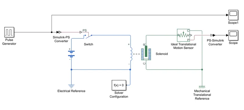
Explanation of block representation :
- Pulse generator is used to produce input signal with change in values of amplitude 1, period in secs 04, pulse width: 50% of period and phase delay in secs 2.
- Simulink-PS converter converts the input signal and transfers the converted signal to the switch.
- We use electrical reference while using electrical blocks in the block arrangement.
- One end of the swich is connected to the battery and other end connected to the solenoid coil.
- The remaining ends of battery and solenoid coil are connected and in that we add the solver configuration of f(x) = 0.
- The solenoid ends of R and S is connected to the Ideal translational motion sensor R and S.
- We have added the mechanical reference due to the use of mechanical blocks.
- To get the output scope we have used PS-Simulink converter for signal conversion.
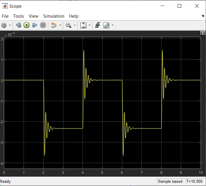
- The output position P is taken from the ideal translational motion and connected to the scope after signal converter to check for the required situation where the switch is closed for two seconds and released.
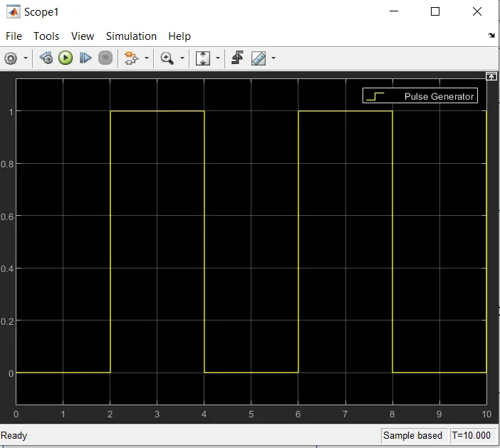
- We have used two scopes here to get the graph of pulse generator and the translational motion position P.
The scope graph :
pulse generation for time 10 seconds, amplitude 1, period(secs) 4, pulse width(% of period) 50,phase delay (secs) 2.
the result output scope showing the posiotion.
Result :
Doorbell model by using solenoid block is done successfully through Simulink.
Conclusion :
The model is made by arranging the required blocks to get the result graph.
We have got the result for the required situation where the switch is closed for two seconds and released has done successfully and the outputs are included.
--------------------------------------------------------------------------------------------------------------------------------------------
Control the temperature of a heater by using thermistor block and the excess temperature will be decreased with help of fan automatically
Aim :
To control the temperature of heater by using thermistor block and the excess temperature is to be reduced to given temperature limit with help of automated on/off fan by using switch.
Objective :
To control heater temperature using thermistor block and to cool excess heat by using temperature control switch connected with fan.
Theory :
Heat control using thermistor is designed to control the temperature of a room, either by using a heat source such as an electric oven heating element or by using a fan or any cooling device.
Thermistors are used as temperature sensors. They can be found in every day appliances such as fire alarms, ovens and refrigerators. They are also used in digital thermometers and in many automotive applications to measure temperature.
The temperature values in the form of heat is converted in the current sensor as current values and we take relevant value as the required temperature value to switch on the fan.
Required blocks :
Signal builder,
Simulink-PS converter,
Controlled temperature source,
Thermal reference,
Solver configuration,
Thermistor,
Battery,
Electrical reference,
Current sensor,
PS-Simulink converter,
Switch,
Constant,
Constant 1,
Scope,
Scope 1,
Scope 2,
Display.
Simulink block arrangement representation :
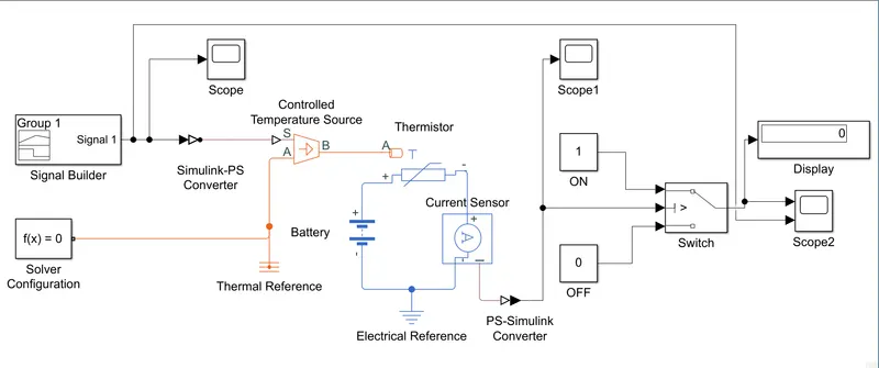
Explanation of block representation :
- Signal builder is used to produce signals as input. In this case we have to create the signals with respect to time and temperature at K.
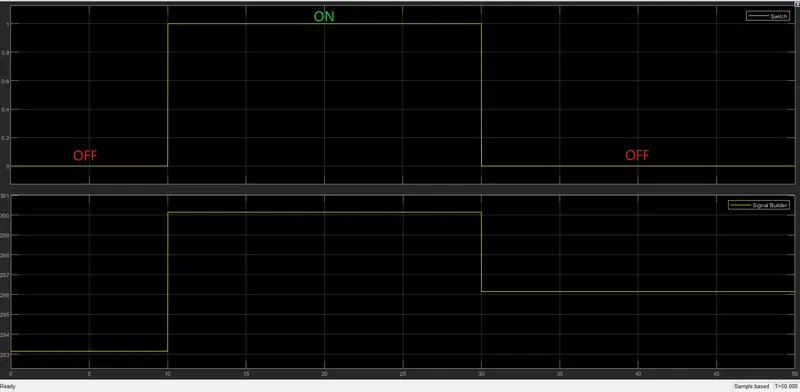
- The required time and temperature values are 0 – 10 secs at 293.15K, 10 – 30 secs at 300.15K and for 30 – 50 secs at 296.15K. In this case we have to switch on the fan when the temperature limit exceeds 298.15K.
- Simulink-PS converter is used to convert and to process the input and in this we have to change input handling – filter and derivatives : filter input, derivatives calculated and input filter order : first order filtering.
- Controlled temperature source is connected and with input signal and it takes the input in S port and the A port is connected with solver configuration, thermal reference.
- The output from controlled temperature source is connected with thermistor and one end of thermistor is connected to battery and other end is connected to current sensor and we connect the battery and current sensor.(Here we have used the current sensor)
- we have attached the electrical reference for electrical blocks.
- We take the output from the current sensor and the signal is transformed by using PS-Simulink converter and we connect to the switch with two constants as o and 1
- The switch has to be configured with the current value which relevant to the temperature value 298.15K.
- The scope and display blocks are attached to get the output values and graph.
The scope graph :
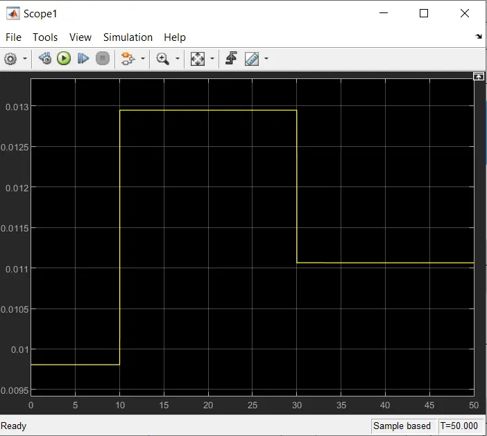
scope graph of current sensor :
output scope compared with input :
Result :
The temperature values are sensed using sensor and while passing through current sensor it is converted into current (amps) value and with the relevant current value to the required temperature we switch on the fan automatically.
This is how we have assigned the blocks and we have got the expected result successfully by using Simulink.
Conclusion :
In this system by using thermistor block and additional required blocks we controlled the temperature of heater at 298.15K successfully.