Week -2
PROJECT-1:
AIM:
To make a simulink model of a door bell using solenoid block.
OBJECTIVE:
- To make a simulink model of a door bell using solenoid block.
- In this model the switch should be closed for every 2seconds and need to ring the bell.
THEORY:
The electric doorbell is a simple circuit that triggers a sound on the completion of circuit by pressing the button. It is this simplicity that makes doorbell such a marvel. The simple devices in the doorbell put the scientific principle of electromagnetism into action in a useful way. In order to understand the operations of an electric bell, you should first need to understand what is an electromagnet. Well, to put it in simple words, an electromagnet is basically a type of magnet in which the magnetic field is produced with the help of an electric current. When any electrical influences electromagnet it works as a standard magnet (generating magnetic fields). When the power generation to an electromagnet stops, the production of the magnetic field also stops. So, in an electric bell, an electromagnet forms an important part along with Armature, Spring, Armature rod, Hammer and a Gong.
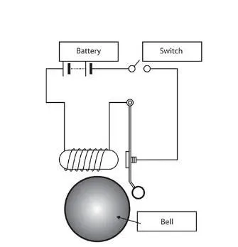
An electric source, for example, a battery can be used to power the electromagnet used in an electric bell. The electric circuit is completed by installing a push switch which you can press to generate sound in an electric bell. The switch also acts as the circuit breaker. So once the setup is completed, when the switch is pressed, the circuit loop is complete which causes the current to flow through the circuit. The arm which strikes the gong is connected to spring at one end and an iron ball at the other end. This is called a hammer or a striker. The arm is attached to an iron strip which is attracted to the electromagnet when the circuit is complete and the current flowing through it. Why does this happen? It’s mainly because the magnetic field created by the electromagnet attracts the iron strip towards it when the circuit is complete. This is the moment when you hear the ringing sound since the hammer keeps hitting the gong. Meanwhile, at its rest position, the hammer is held away from the gong on account of the spring attached to its arm. This is an anchored arm.
SIMULINK MODEL:
BLOCKS USED IN MODEL:
- Pulse generator
- Scope
- Simulink-ps converter
- SPST Switch
- Battery
- Electrical references
- Solenoid
- Ideal translational motion sensor
- Mechanical translational resference
- PS-Simulink converter
- Scope1
- Solver configuration
EXPLANATION:
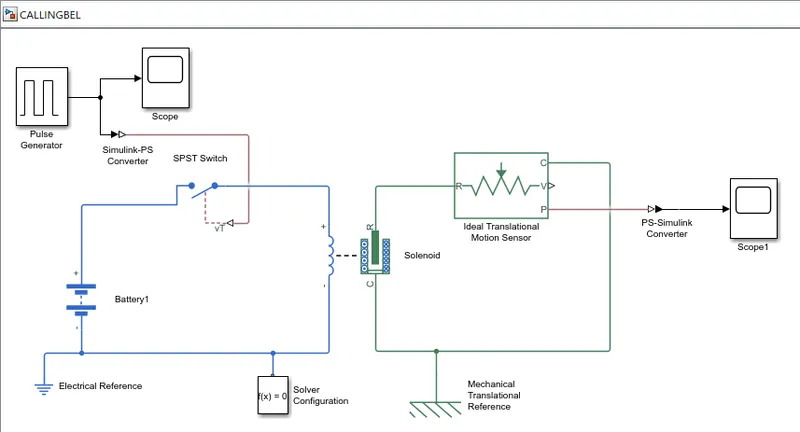
- In the above model of door bell we need to select the reqired blocks as per the given conditions.
- we used 12 blocks for this model.
- Firstly we need to select the solenoid block as it is the basic reqirement from the given conditions.
- Solenoid block is used for converting electromagnetic waves in th mechanical properties.
- We have taken battery from the library and connected negative terminal of battery to solenoid block.
- In between solenoid block and battery we need to place switch from the library
- Positve terminal of the solenoid is connected to switch.
- Positive terminal of battery is also connected to switch.
- To operate we need to give signals so we connected PS block to switch.
- To get the signals to switch we used the pulse generator block to form square signals to open and close the switch for every 2 sec.
- We need to connect the Electrical resistence block to the negative terminal of the battery, it acts as a earthing to the model.
- Now the solenoid block ports R and C are connected to Ideal translational sensor block.
- Solenoid block R is connected to the input port of the ideal translational sensor block port R
- Solenoid block port C is connected to the output port of the ideal translational sensor block port C.
- Solenoid block port C is connected to mechanical reference which acts as fixed point of the solenoid.
- The output signal of solenoid block port P is connected to scope for generating output signals.
- In between port p and scope we need to connect PS-simulink converter block.
- we have used pulse generator for giving signal to switch to form a square signals we need to edit the parametrs of the pulse geneartor for reqire wave form.
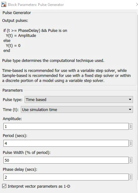
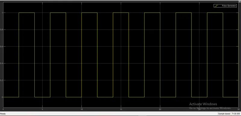
- In block parameters block we have seen that we have given amplitude as '1' period as 4sec,pulse width as 50%,phase delay as 2sec.In out put of the signals, the signals will start after 2 sec because we ahve given phase delay as 2 sec.After 2sec it will raise to 1 from zero as we have given amplitude as 1 by default.The signal will be active up to 2sec as we given pulse width as 50% of period.after 2 sec which means total after 4sec it again comes to zero line and the same process repaets upto given run time we have given for 30 sec.
- This pulse generator is connected to scope for genearting the output.
- we can see the output from the scope.
- Now the port P of the mechanical translational block is connected to the scope block, in between we have connected PS-simulink converter block.
- By double clicking the scope block we can obtain output of the model after running the model
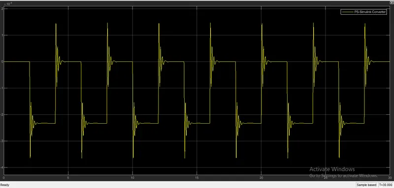
OUTPUTS OF THE MODEL:
CONCLUSIONS:
Simulink model of the door bell using solenoid block, where the switch is closed for 2sec and release is successfully created.
PROJECT-2:
AIM:
To make the simulink model of a heater to sense the temperature and turn on or off the fan.
OBJECTIVE:
To make a model to sense the temperature and turn on/off of the fan according to the given conditions i.e, to ON the fan if the temperature is above the 25 degress otherwise OFF the fan.
Theory:
Thermister is atype of resistor whose electrical resistance varies with the temperature. Thermister acts as a passive component in the circuit.They are accurate,cheap and rebust way to measure temperature.The working principle of a thermistor is that its resistance is dependent on its temperature. We can measure the resistance of a thermistor using an ohmmeter. If we know the exact relationship between how changes in the temperature will affect the resistance of the thermistor – then by measuring the thermistor’s resistance we can derive its temperature.How much the resistance changes depends on the type of material used in the thermistor. The relationship between a thermistor’s temperature and resistance is non-linear.
There are two types of thermistors:
- Negative Temperature Coefficient (NTC) Thermistor
- Positive Temperature Coefficient (PTC) Thermistor
NTC Thermistor
In an NTC thermistor, when the temperature increases, resistance decreases. And when temperature decreases, resistance increases. Hence in an NTC thermistor temperature and resistance are inversely proportional. These are the most common type of themistor.
PTC Thermistor
A PTC thermistor has the reverse relationship between temperature and resistance. When temperature increases, the resistance increases. And when temperature decreases, resistance decreases. Hence in a PTC thermistor temperature and resistance are inversely proportional. Although PTC thermistors are not as common as NTC thermistors, they are frequently used as a form of circuit protection. Similar to the function of fuses, PTC thermistors can act as current-limiting device.
BLOCKS USED IN MODEL:
- Signal builder
- Simulink - ps converter
- Controlled temperature source
- Thermal resistance
- Thermister
- Battery
- Solver configuration
- Resistor
- Electrical reference
- scope
- switch
- voltage source
- constant
SIMULINK MODEL:
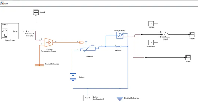
EXPLANATION:
- To create a thermister fan main blocks required are Signal builder, Simulink - ps converter, Controlled temperature source ,Thermal resistance ,Thermister ,Battery ,Solver configuration, Resistor, Electrical reference ,scope, switch ,voltage source ,constant.
- First a thermister block is taken from library.
- Battery is placed and positive terminal of battery is connected to the positive terminal of thermister block.
- Now place resistor from the library and positive terminal is connected to negative terminal of thermister.
- Negative port of resister is connected to negative terminal of battery.
- Now electrical reference is connected to negative terminal of battery which acts as a earthing to the model.
- Now connect voltage senser block parallel to the resistor to measure the voltage sensor.
- Now we need a phisical signals to the thermister as per the given conditions.so we place control temperature source.
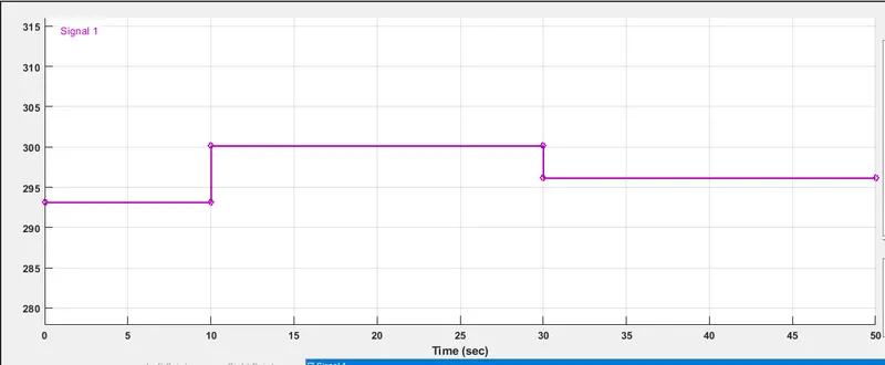
- To this contrl temperature source we need to given input values at different tempeature with time so we used signal builder block.
- By doulbe clicking the signal builder block we need to design the block as per the reqirement.
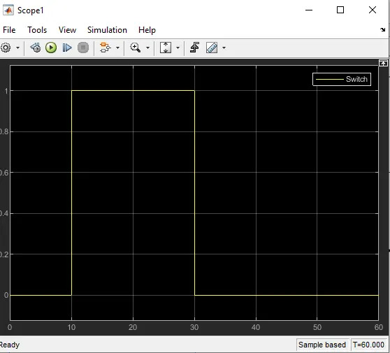
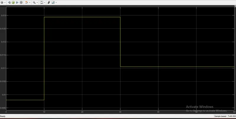
- we need to add the switch block to the model which is connected to the voltage sensor block.
result:
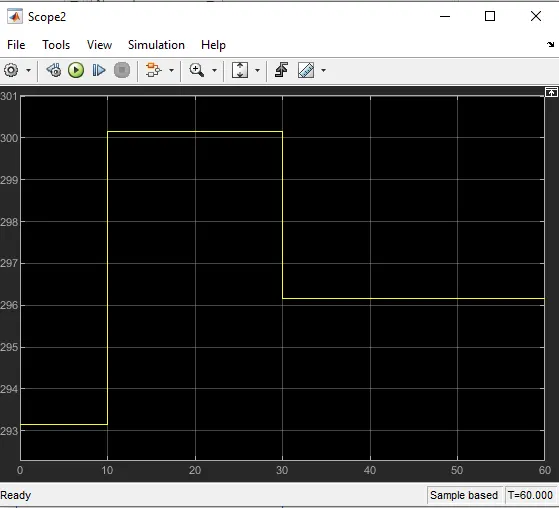
conclusion:
Sinulink model by using thermister, fan should ON/OFF based on the temperature as per the given conditions were designed and sucessfully running.