Week -2
Report
AIM:
- Make a Simulink model of Doorbell using solenoid block:
- Use a thermistor to sense the temperature of a heater & turn on or turn off the fan as per the conditions:
1] Make a Simulink model of Doorbell using solenoid block:
Given Condition:
- when the switch is closed the electromagnet receives electrical power from the battery and pulls the metal arm to hit the bell producing sound.
- Create a situation where the switch is closed for 2 seconds and then released. Observe the physical movement of the plunger.
Reference Model:
Simulink Model:
Explanation of Simulink Model:
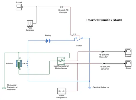
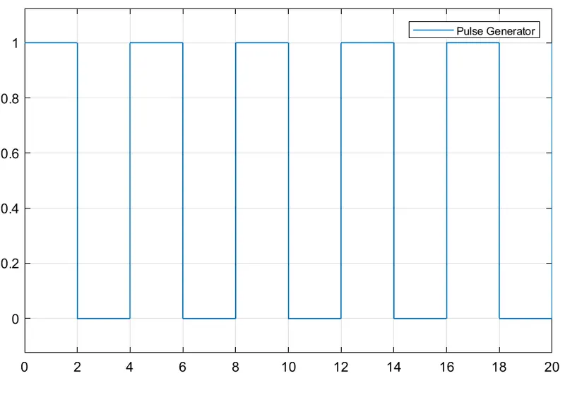
- for Creating a situation where the switch is closed for 2 seconds and then released so that we use the pulse generator.time based pulse we output pulse we generate for 20 sec.simulation time period.in which amplitude of pulse is 1.and period for 1 pulse is 4 second and pulse width is 50% period its mean for 2 second pulse is on.and we decide no phase delay in pulse generator.
- scope1 used to showing input pulse.
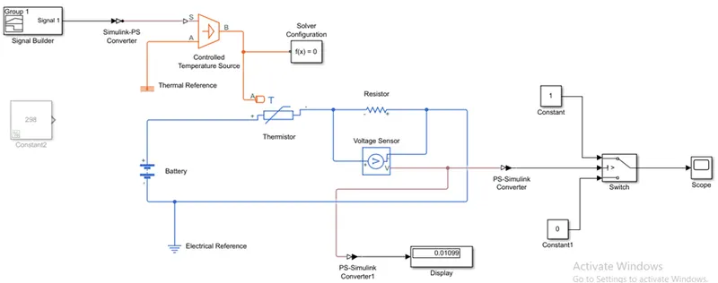
- after that we use after that we use the simulink-ps convertor so its Converts the Simulink input signal to a Physical Signal.
- after that we use switch for give periodic pulse to solenoid for operating plunger movement.in which we select the threshold value is 0.5.it means the if amplitude of pulse is greater then the this threshold value then and then only switch is closed.and circuit is complete otherwise switch is open and for that perticular time period electric signal goes to solenoid and movement of plunger is happen.switch is connect to negative terminal of battery and positive terminal of solenoid.
- after that we use the battery,positive terminal battery is connect to negative terminal of solenoid.and switch is connect to negative terminal of battery.in this If you select Infinite for the Battery charge capacity parameter, the block models the battery as a series [internal resistance=2 ohm] and a [constant voltage=12 v] source.
- solenoid This block implements the electrical and mechanical characteristics of a solenoid. Parameterization is in terms of two points [X1,F1] and [X2,F2] on its force-stroke curve for a 100 percent duty cycle at Rated voltage Vdc and Rated current Idc where X2>X1>0 are stroke values and F1>F2>0 are corresponding forces.in this R port of solenoid connect to R port of ideal translation motion sensor.if switch is closed then plunger movement happen in solenoid and is sense by motion sensor.and C port of solenoid connect to C port of ideal translation motion sensor.
- also we use mechanical translational reference and electrical reference.
- after that we use ideal translational motion sensor block.if switch is closed then plunger movement is happen into solenoid and its sense by motion sensor.and C port of solenoid connect to C port of ideal translation motion sensor.
- after that we use the ps-simulink convertor for converts the input Physical Signal to a Simulink output signal.
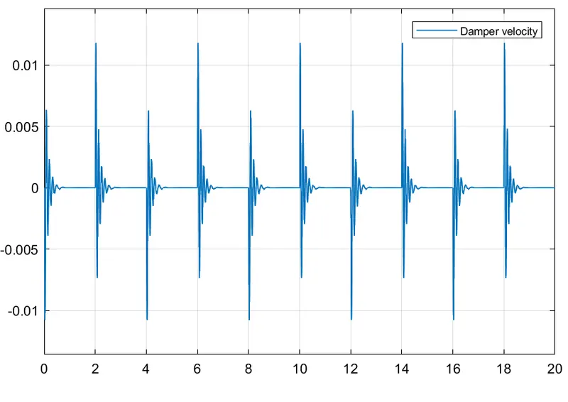
- lastly we use two scope for getting output result.scope for Displacement of plunger and scope 2 for output damped velocity.
Result:
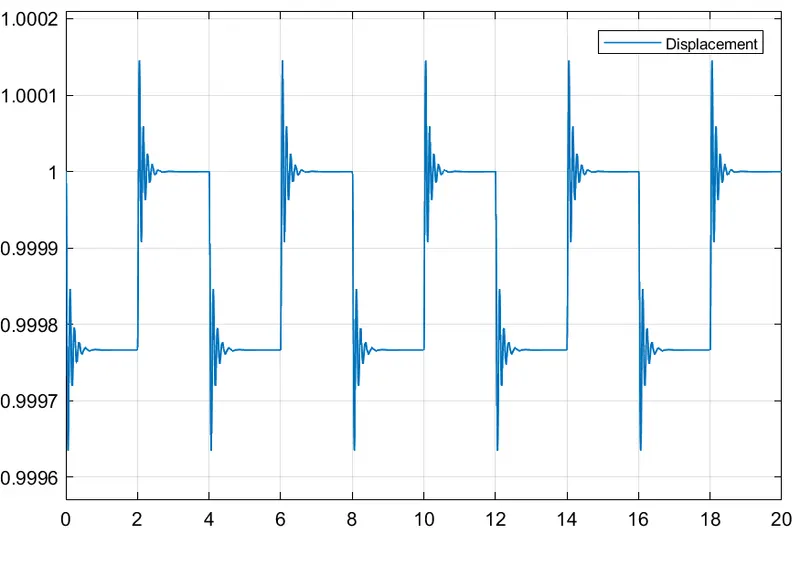
time period given is 2 sec.to the pulse generator to open and close the switch.when the switch is closed the solenoid block receive electric power from battery and plunger move from port R to C to hit the bell and produce sound.otherwise switch is open and circuit is breck.
1] Input pulse generator:
2] Displacement of plunger:
3] output damped velocity:
2] Use a thermistor to sense the temperature of a heater & turn on or turn off the fan:
Given condition:
Temperature source: 20 °C from 0 to 10 seconds
27 °C from 10 to 30 seconds,
23 °C from 30 to 50 seconds
Fan conditions: ON if the temperature above 25 °C, OFF otherwise
Simulink Model:
Explanation of Simulink Model:
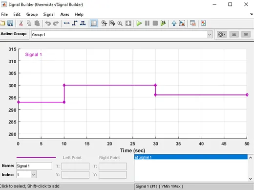
- as per given input condition we create the pulse in Signal Builder.in which total time period is 50 second and 0-10 seconds temperature value is 293k and next 20 seconds temperature value goes to 300k and last 20 seconds value of temperature is 296 k.signal builder shown below.
- after that we use the simulink-ps converter its Converts the Simulink input signal to a Physical Signal.
- after that we use the controlled temperature source This block represents an ideal energy source in a thermal network that can maintain a controlled temperature difference regardless of the heat flow rate. The temperature difference is set by the physical signal port S. A positive temperature difference causes the temperature at port B to be greater than the temperature at port A. also we use the thermal reference and its connect to the A port of controlled temperature source.
- after that we use the thermister its general behavoir is decreases the resistance when temperature is increased.there are two type NTC(negative temperature co-efficients)its means the when temp.is increased then resistance is decreased and PTC(positive temperature co-efficients) its means the when temp.is increased then resistance is increased. The temperature T of the thermistor is governed by the equation m*c*dT/dt = Q where Q is the net heat flow into port A, m is the mass and c is the lumped specific heat capacity.
- after that we use the resister series with thermister The voltage-current (V-I) relationship for a linear resistor is V=I*R, where R is the constant resistance in ohms.The positive and negative terminals of the resistor are denoted by the + and - signs respectively.
- parallel to the resister we connect the ideal voltage sensor This block represents an ideal voltage sensor, that is, a device that converts voltage measured between any electrical connections into a physical signal proportional to the voltage.
- also we use the battery and electric referance along with we use the ps-simulink converter and display use.
- V port of ideal voltage sensor is connect to ps-simulink converter after its connect to switch in this Pass through input 1 when input 2 satisfies the selected criterion; otherwise, pass through input 3. The inputs are numbered top to bottom (or left to right). The first and third input ports are data ports, and the second input port is the control port. The criteria for control port 2 are u2 >= Threshold, u2 > Threshold or u2 ~= 0.
- first insted of signal builder we use the constant block to set the thresold value in switch at 298k and then run the simulink model after that in display we got the voltage value for 298 k and copy that value and put this voltage value in switch set as thresold value and again use the signal builder and run the simulink model
- last in scope we observe the result.
Result:
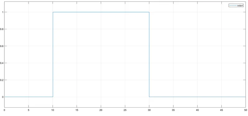
- x axis shown that the time periods and y axis show that 1 means the fan is in ON condition and 0 means the fan is in OFF condition.
- for 0-10 seconds fan is OFF condition because temperature is 293 k which is below than the threshold value 298k.
- after that 10-30 seconds temperature goes to 300k then swich will be ON condition because of temperature value is more then the threshold value.
- after that 30-50 seconds temperature goes to 296k then swich will be OFF condition because of temperature value is less then the threshold value.