Week -2
Door Bell:
Aim: Make a Simulink model of Doorbell using a solenoid block.
Conditions: The switch is closed for 2 seconds and then released.
Blocks used in the Model:
- Pulse Generator
- Scope
- Switch
- Battery
- Solenoid
- Simulink-PS converter
- PS-Simulink converter
- Ideal Translational Motion Sensor
- Mechanical Translational Reference
- Electrical Reference
- Slover Configuration
Simulink Model:
Model Explanation:
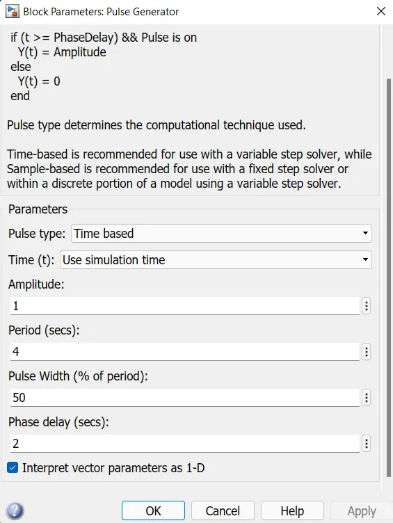
A pulse generator is given as input with the following specifications. The condition was that the bell is engaged for 2 seconds and then released. The same was implemented by giving a period as 4 Seconds and pulse width as 50% of 4 seconds, i.e., 2 seconds. Phase delay was given as 2 seconds, so the simulation starts from the unengaged condition of the switch.
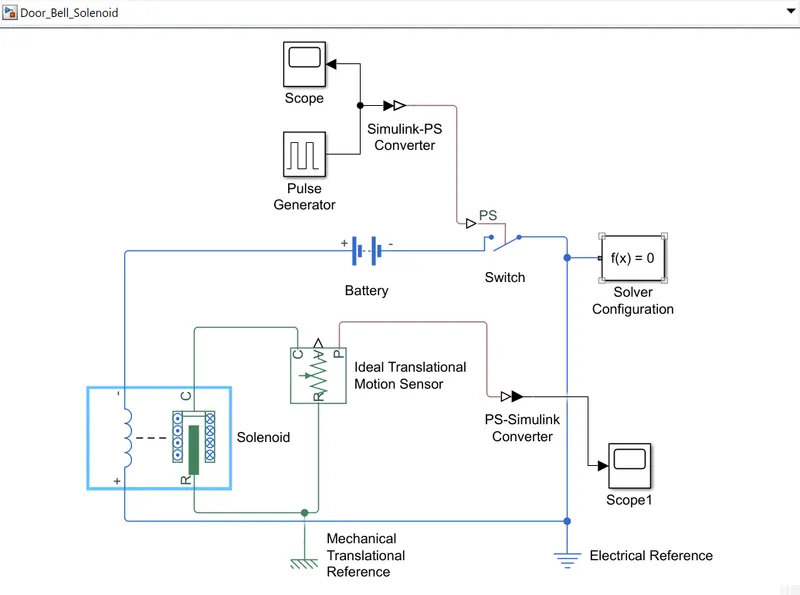
The signal from the pulse generator was converted using a Simulink-PS converter and is given as an input to switch. A solenoid is introduced and the battery is connected to it. The voltage of the battery connected as made as to the same as that of the rated voltage of the solenoid. The Sitch is also connected to the same circuit. The position of the solenoid plunger is measured using an ideal translational motion sensor connected to the circuit. The initial position was set to 5mm in the translational motion sensor. both mechanical and electrical references were connected to the respective circuits. The output from the ideal translational motion sensor is converted using a PS-Simulink converter and is given to the scope to display the results. The scope was also connected to the input to visualize its behaviour. The spring constant and damping parameters of the solenoid block was altered to obtain the desired graph.
Input Signal:
Result:
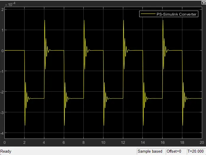
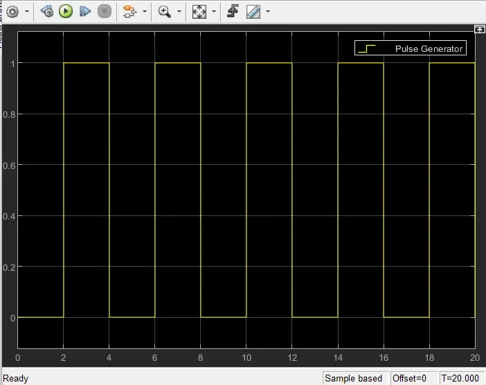
The simulation has run for 20 seconds and the result obtained is shown above. It can be observed that at each 2 seconds interval the bell is ringing.
Thermistor:
Aim: To use a thermistor to sense the temperature of a heater and turn on or off the fan.
Conditions:
- Input:
- 0 to 10-sec temp is 20 °C
- 10 to 30-sec temp is 27 °C
- 30 to 50-sec temp is 23 °C
- Output:
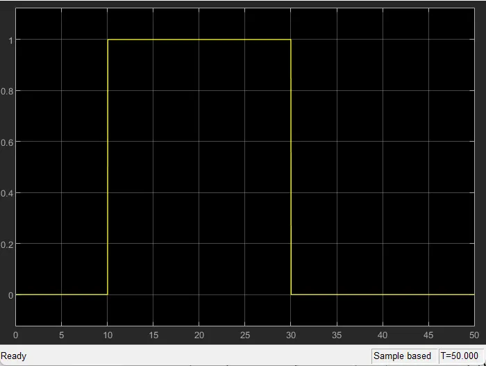
- The fan should be ON only>25 °C else OFF
Blocks used in the model:
- Repeating Sequence Stair - to generate the signal according to the input condition given.
- PS-Simulink Converter: Converts Simulink signals to the respective physical signal.
- Simulink-PS Converter: Converts physical signals to the respective Simulink signal.
- Controlled Temperature Source(CTC): Provide a temperature physical output based on the condition given to port S.
- Thermal Reference: It provides the required initial conditions to the connected thermal block for the solver.
- Thermistor: block shows u the NTC thermistor relation between temperature and resistance.
- Battery: is a storage device that provides the required voltage based on the parameter given.
- Resistor: provides the opposing nature of the current in a circuit.
- Voltage Sensor: used to measure the voltage or potential difference across any electrical component and it should connect in parallel only.
- Solver Configuration: specifies the solver parameters that the model needs before beginning simulation and this is mandatory for all Simscape designs.
- Constant: Provides a constant output value.
- Switch: used from the library Simulink/Signal Routing here it has three inputs namely Port1, Port2 and Port3. Port 2 is a control input where the signal given to Port2 is satisfied with the condition and threshold of the switch block then it passes Port1 as output and if it is not satisfied then it will pass Port3 as output.
- Scope: is an output block that shows the signal with respective time in an X-axis.
Procedure:
- A Repeating Sequence Stair is given to the thermistor through a controlled temperature source. The definition of the Repeating Sequence Stair block is given below.
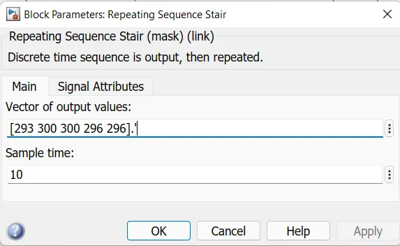
- The condition of the temperature source is defined inside the above window. The sample time was taken as 10sec and the whole simulation time was taken as 50sec.
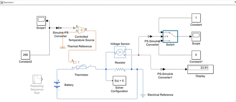
- The battery and a resistor are connected in the thermistor circuit. A voltage sensor was given across this resistor to measure the voltage change during different temperature inputs. The resistance of this resistor can be set to any value, but it should not be changed once the threshold voltage is found.
- The threshold temperature was given as 25°C or 298K. Applying the constant value of 298 to the model removing the Repeating sequence stair and finding out the value of the result. Put that result value in the switch as the threshold value.
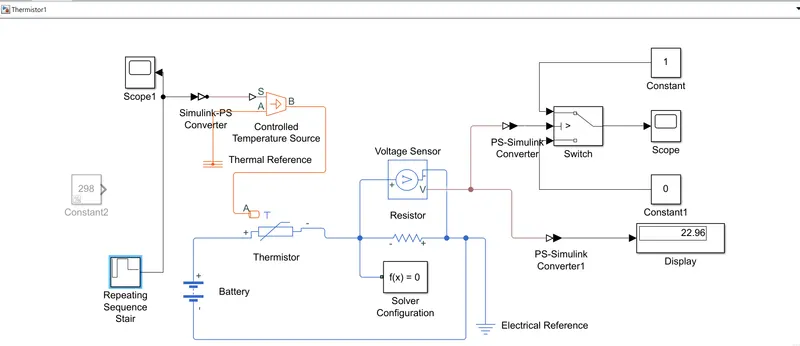
- Remove the constant block, connect the Repeating Sequencing Block with the value given and run the simulation.
Result in Graph: