Week -2
Task 1
Aim : To make a Simulink model of Doorbell using a Solenoid block.
Objective :
To make a Simulink model of Doorbell using solenoid block with the following details:
In the arrangement, when the switch is closed the electromagnet receives electrical power from the battery and pulls the metal arm to hit the bell producing sound.
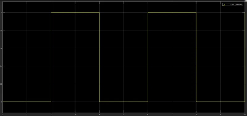
Create a situation where the switch is closed for 2 seconds and then released. Observe the physical movement of the plunger.
MODEL:
1.Physical model of the Doorbell :
How they work
The most widely used form is the interrupter bell, which is a mechanical bell that produces a continuous sound when current is applied. See animation, above. The bell or gong (B), which is often in the shape of a cup or half-sphere,b is struck by a spring-loaded arm (A) with a metal ball on the end called a clapper, actuated by an electromagnmet (E). In its rest position the clapper is held away from the bell a short distance by its springy arm. When the switch (K) is closed, an electric current passes from the battery (U) through the winding of the electromagnet. It creates a magnetic field that attracts the iron arm of the clapper, pulling it over to give the bell a tap. This opens a pair of electrical contacts (T) attached to the clapper arm, interrupting the current to the electromagnet. The magnetic field of the electromagnet collapses, and the clapper springs away from the bell. This closes the contacts again, allowing the current to flow to the electromagnet again, so the magnet pulls the clapper over to strike the bell again. This cycle repeats rapidly, many times per second, resulting in a continuous ringing.
The tone of the sound generated depends on the shape and size of the bell or gong resonator. Where several bells are installed together, they may be given distinctive rings by using different size or shapes of gong, even though the strike mechanisms are identical.
Another type, the single-stroke bell, has no interrupting contacts. The hammer strikes the gong once each time the circuit is closed. These are used to signal brief notifications, such as a shop door opening for a customer, rather than continuous warnings.
Simulink model of Solenoid Doorbell :
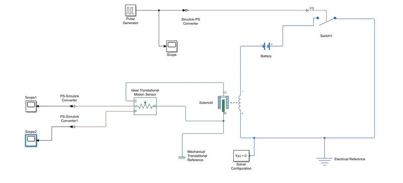
Working of Doorbell model with Solenoid using Simulink :
1. Initially we use Pulse Generator to give the input condition as per the question. 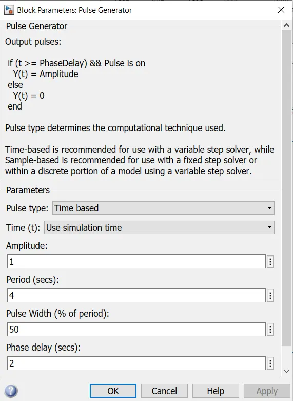
2. The Pulse generator gives a simulinlk input signal which is changed to physical signal by the Simulink-PS converter.Then a scope is connected to see the input signal.
3. The Simulink-PS converter is connected to a switch.The block represents a switch controlled by an external physical signal. If the external physical signal PS is greater than the threshold, then the switch is closed, otherwise the switch is open.
4. Then the switch is connected to a Solenoid along with a battery and the circuit is also connected with a Electrical refference and a solver equation.
5.Then the R port of the solenoid is connected to the R port of the Ideal translational motion sensor and the Cport of the solenoid is connected to the C port of the Ideal translational motion sensor. This block measures velocity or displacement in a mechanical translational network.
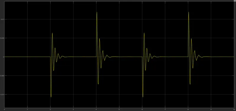
6.The physical signal ports V and P report the velocity and position, respectively, of port R relative to port C. The measured velocity is positive when the velocity at port R is greater than the velocity at port C.
7.Since the physical signal ports gives the physical signals it is connected to scopes by the PS-simulink converter to chnge to simulink inout signal.
Output :
Pulse generated as input signal :
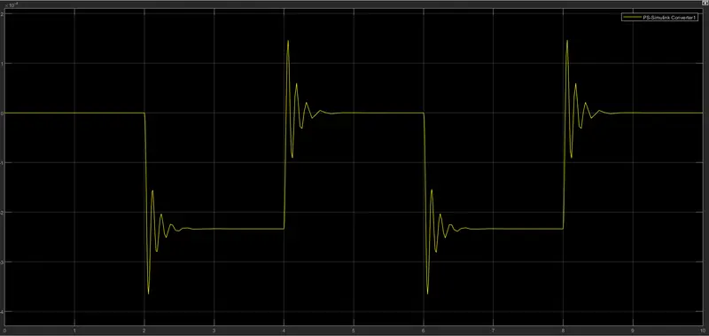
Velocity :
Position :
Conclusion :
Thus, the model of a doorbell is created in simulink as per the input conditions and the physical movement of the plunger is observed sucessfully.
Task 2
Aim :
To build a simulink model using thermistor to sense the temperature.
Objective :
Use a thermistor to sense the temperature of a heater & turn on or turn off the fan as per the below conditions:
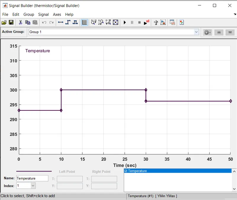
Temperature source: 20 °C from 0 to 10 seconds, 27 °C from 10 to 30 seconds, 23 °C from 30 to 50 seconds
Fan conditions: ON if the temperature above 25 °C, OFF otherwise
Theory :
Thermistor is a type of resistor whose resistance is strongly dependent on temperature, more so than in standard resistors. The word is a combination of thermal and resistor. Thermistors are widely used as inrush current limiters, temperature sensors (negative temperature coefficient or NTC type typically), self-resetting overcurrent protectors, and self-regulating heating elements (positive temperature coefficient or PTC type typically). An operational temperature range of a thermistor is dependent on the probe type and is typically in between −100 ⁰C and 300 ⁰C
Simulink Model of the Thermistoe setup :
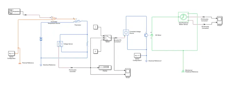
Explanation :
1. Initially the signal builder is used to generate the simulink input signal where it is 293.15 from 0 to 10 seconds and 300.15 from 10 to 30 seconds and 296.15 from 30 - 50 seconds then it is connected to a Controlled Temperature source block through a Simulink-PS converter to convert it to a physical signal.
2. This block represents an ideal energy source in a thermal network that can maintain a controlled temperature difference regardless of the heat flow rate. The temperature difference is set by the physical signal port S. A positive temperature difference causes the temperature at port B to be greater than the temperature at port A. This block is then connected to a Thermal refference where the temperature is equal to absolute zero.
3. Since a thermistor is a type of resistor whose resistance is strongly dependent on temperature, a resistor is connected to the negative terminal of the thermistor and ato measure the voltage across the resistor a voltage sensor is also connected and a battery is connected is also connected to the negative terminal of the thermistor and also a electrical refference.
4. And from the voltage sensor its is then connected to a display, scope and a switch through a PS-simulink converter. The scope and displays the resultant from the voltage.
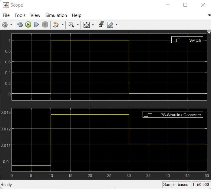
5. From the graph we can get a Thershold value to give to the switch. So we keep the thershold value as 0.01106. So the switch passes through input 1 when input 2 satisfies the selected criterion; otherwise, pass through input 3. The inputs are numbered top to bottom (or left to right). The first and third input ports are data ports, and the second input port is the control port. The criteria for control port 2 are u2 >= Threshold, u2 > Threshold or u2 ~= 0.
6. Then the output from the switch is given to the Controlled voltage source.This block represents an ideal voltage source that is powerful enough to maintain the specified voltage at its output regardless of the current passing through it. The output voltage is V = Vs, where Vs is the numerical value presented at the physical signal port.
7. Then this is connected to the DC motor through a Solver configuration and a electrical refference.The the DC motor is connected Ideal Rotational motion sensor to see hoe the DC motor reponds to the input. And the it is connected to a Mechanical refference.
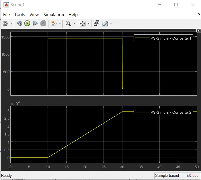
8. So from the graph it is clear that based on the given input condition the fan should only eork from 10 to 30 seconds which has temperature 25 degree.
Conclusion :
Thus, a thermistor model in simulink is created sucessfully.