Week -2
AIM:
To Create a Simulink model of a doorbell using a solenoid block, as well as a Simulink model that uses a thermistor to sense the temperature of a heater and turn off the fan.
OBJECTIVE:
- Make a Simulink model of Doorbell using a solenoid block with the following details:
In the above arrangement, when the switch is closed the electromagnet receives electrical power from the battery and pulls the metal arm to hit the bell producing sound. Create a situation where the switch is closed for 2 seconds and then released. Observe the physical movement of the plunger. Assume remaining parameters.
- Use a thermistor to sense the temperature of a heater & turn on or turn off the fan as per the below conditions:
Temperature source: 20 0C from 0 to 10 seconds,
27 0C from 10 to 30 seconds,
27 0C from 30 to 50 seconds,
Fan conditions: ON if the temperature is above 25 0C, OFF otherwise.
THEORY:
Doorbell:
A doorbell is a signalling device that is usually located near a door to a building entrance. When a visitor clicks a button, a bell rings inside the building, notifying the occupant of the presence of the visitor. As electromagnet is the heart of a doorbell. Wire coils are wrapped around a small piece of magnetic metal to make electromagnets. A magnetic field is created around a wire, as electricity travels through it. When you press the internal electromagnet of a doorbell. The electromagnet’s magnetic field is then employed to power a doorbell–sounding device.
Doorbells are low-voltage devices. This implies they only use a small amount of energy to function. A crucial component of a doorbell mechanism is the transformer. A standard 120-volt is used in regular home electricity is converted to the lower voltage required by the doorbell via the transformer.
Solenoid:
A solenoid is a 3-dimensional wire structure. When the wire is wound around a metallic block in a coil and electricity is transmitted through it, it acquires certain unique magnetic properties. Electromagnetic induction makes it an electromagnet that can be switched on or off. The side in which the current appears to be passing clockwise is the south pole and the side in which the current seems to be passing anticlockwise is the Northern pole. The solenoid works just like a bar magnet and therefore has many uses. This principle is used to create values, among other things. A relay is used when a solenoid controls an electric switch.
FIG 1: Simple Diagram of Doorbell
OBJECTIVE-1:
SIMULINK MODEL:
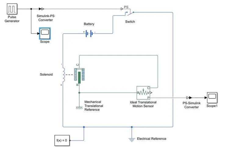
FIG 2: Simulink model of Doorbell
The FIG 2 represents “A doorbell operated on the solenoid.” In this model, some blocks are used to make the working model of the doorbell. These blocks are:
Model Explanation:
- The pulse generator is used to give the signal input where Amplitude=1, period=4 sec, Pulse width=50% and Phase delay=2 sec.
- The input signal is then translated into physical form with the use of the “Simulink-PS Converter” before being sent to the switch of the electrical circuit.
- A solenoid, a battery, and a switch make up the electrical circuit. The solenoid’s one end is connected to the battery, while the other is attached to the switch. An electrical reference is provided in the electrical circuit.
- The mechanical component of the solenoid is coupled to a mechanical translational reference and ideal translation motion sensor.
- To deliver the output in signal form, the sensor’s P-port connects to the “PS-Simulink Converter”. The converter is also attached to a scope, which displays our output signal.
- Before starting the simulation, a solver configuration is attached to an electrical circuit to solve all parameters.
Screenshot of INPUT values:
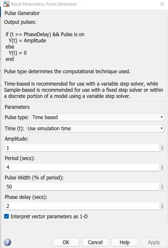
FIG 3: Input Values of Pulse Generator
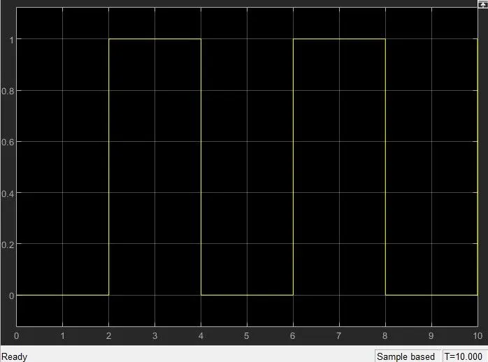
FIG 4: Input Scope
Output:
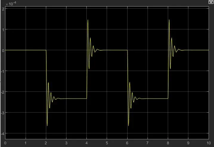
FIG 5: Output Scope
OBJECTIVE-2:
THEORY:
A thermistor is a resistor whose electrical resistance changes in response to temperature Variations. Although all resistance of all resistors varies slightly with temperature, the resistance of a thermistor is more sensitive to temperature variations.
In a circuit, thermistors serve as a passive component. They are a reliable, accurate, and inexpensive technique to detect temperature. Even though thermistors do not operate well in severe heat or cold, they are the sensor of choice for a wide range of applications.
SIMULINK MODEL:
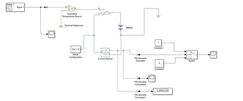
FIG 6: Simulink model of Thermistor
Model Explanation:
- The signal is initially constructed in “Signal Builder” before being passed to “Simulink-PS Converter” to be converted into the physical signal.
- The “Controlled Temperature Source” block is connected to this physical signal. This block is connected to the thermistor and a “Thermal Reference” block.
- The thermistor is a component of an electric circuit that includes a battery, a current sensor, and an electrical reference Before the simulation begins, a solver configuration is linked to the electrical circuit to solve all parameters.
- The voltage sensor detects temperature as voltage and communicates the information to its port “V”.
- We retrieve our output from this port and deliver it to two distinct “PS-Simulink Converters”.
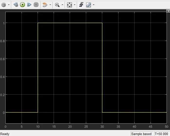
- The signal is delivered from converter-1 to the threshold switch. The threshold limit of the switch is set at 1.1055e-02. If the temperature is more than or equal to the threshold limit, the output is “1”, which means “Switch on”. If the temperature falls below the setpoint, the output will be “0”, which signifies “Switch Off”. A “Signal Builder” block is used to produce the input signal.
- We can see the output plot on the scope because the switch is connected to it.
- From converter-2, the physical signal is converted into a Simulink signal, and the voltage data from the Voltage Sensor is sent to the display. This display shows the voltage threshold value. The switch determines its value.
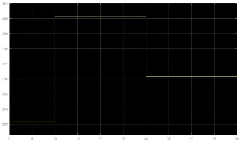
Screenshot of INPUT values:
OUTPUT:
EXPLANATION OF THE BLOCKS USED IN SIMULINK:
- Pulse Generator: At regular intervals, the Pulse Generator block creates square wave pulses. The shape of the output waveform is determined by the block, waveform parameters like amplitude, pulse width, period, and phase delay.
- Simulink-PS Converter: The unitless Simulink input signal is converted to a Physical Signal.
- Scope: During simulation, signals are created and shown.
- Switch: An external physical signal is used to operate the switch.
- Battery: A basic battery model is represented by the battery block.
- Solenoid: Model the solenoid’s electrical properties and produce force.
- Ideal Translational Motion Sensor: As a block parameter, the ideal Translational Motion Sensor describes a device that turns an across variable sensed between two mechanical translational nodes into a control signal proportional to velocity or position. The sensor is perfect since it ignores inertia, friction, delays, energy consumption, and other factors.
- Mechanical Translational Reference: All Mechanical Translational Ports that are tightly attached to the frame must be linked to a Mechanical Translational block, which is represented by the Mechanical Translational Reference Block.
- Electrical Reference: An electrical ground is represented by the Electrical Reference block. All blocks that are directly linked to the ground must have their electrical conserving ports connected to an Electrical Reference block. At least one electrical Reference block must be included in each model incorporating electrical elements.
- Slover Configuration: Before you can start the simulation, you must provide the solver settings in the solver configuration box.
- PS-Simulink Converter: Create a Simulink output signal from a physical signal.