Photo Realistic Rendering
AIM:
To Design an American Chopper in Solidworks & Photo Realistic Rendering.
OBJECTIVE:
The objective of this project is to utilize SOLIDWORKS to model the parts and explore the tools that are used in this module.
- Designing individual components.
- Assembling the American Chopper using Mating Relationships.
- Creating appropriate decals, scenes, lighting, and cameras.
- Using SOLIDWORKS (Photo view 360 & visualize), render the assembled Chopper
INTRODUCTION:
The world we live in now is not the same as it was 50 years ago. This is a reality that we cannot reject at all. It occurs all the time. It will take place regardless of the time zone. Science and engineering have made it feasible.
As we all know, the first stage in creating any product is to design it. We may save a lot of resources such as money, materials, human resources, and electricity by developing a product instead of using traditional methods.
Were designing an American Chopper, which is one most famous bikes of all time.
DESIGN METHODOLOGY/ APPROACH:
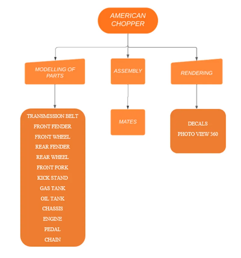
DESCRIPTION:
Commands Used:
2D & 3D Sketch tools:
- Line: This feature allows us to create a straight line.
- Circle: This feature allows us to create circles.
- Rectangle: This feature allows us to create rectangles.
- Spline: This allows us to make curved lines.
- Arc: This allows us to make curved lines.
- Trim: This is used to trim Sketches
- Extend: This feature allows us to extend the sketches.
- Linear sketch pattern: This allows us to create a pattern in a straight line or to set an angle.
- Fillet: This is used to create a circular edge.
- Mirror entities: This is used to create a Mirror of Sketch.
- Convert entities: This is used to sketch entities to sketch segments.
- Offset entities: This is used to offset the faces, edges at a distance or angle.
- Split entities: This is used to split a line into two or more parts.
Features:
The features contain the sub-options like blind, up to the surface, up to vertex, offset from the surface, up to the body, and midplane.
- Extrude Boss/Base: This feature is to create a solid body. You need to obtain your sketch and select the sub-options in which type or which direction you need to create.
- Revolved Boss/Base: This feature is to create a solid body. You need to obtain your sketch and select the sub-options in which type or up to which angle you need to create.
- Swept Boss/Base: This feature is to create a solid body. You need to create the two Sketches; the first sketch represents the circular path and the second sketch represents the up to which direction need to create.
- Extrude Cut: This feature is to Cut the body. You need to obtain your sketch and select a contour area that needs to be cut, select the sub-options in which type or which direction need to cut the body.
- Fillet: This is used to create a circular edge on the solid body.
- Chamfer: This is used to create a flat edge on the solid body. You need to obtain your sketch and select the sub-options in which type you need to create.
- Shell: This is used to create a shell thickness of the solid body by selecting the faces that need to shell.
- Mirror: This is used to create a Mirror of a body by selecting a reference of the face or plane.
- Plane: This is used to create a plane in which type or which direction you need to create.
- Projected curve: This is used to create a curve. You need to create two Sketch’s to project the curve.
- Dome: Select one or more planar or non-planar faces. You can also create an elliptical dome at a distance.
- Combine: Select the bodies to combine two bodies into one body.
- Split: The split line is used to divide parts into multiple bodies. You can split the line feature to save the new bodies when you split the part or use the save bodies to save them after the split is complete.
Surfaces:
- Extruded Surface: This feature is to create a Surface. You need to obtain your sketch and select the sub-options in which type or which direction you need to create.
- Revolved Surface: This feature is to create a Surface. You need to obtain your sketch and select the sub-options in which type or up to which angle you need to create.
- Swept Surface: This feature is to create a Surface. You need to create the two Sketches; the first sketch represents the circular path and the second sketch represents the up to which direction need to create.
- Lofted Surface: This feature is to create a Surface. You need to create four Sketches; the first two sketches represent the profiles and the second two sketches represent Guide curves.
- Filled Surface: This feature is to create a Surface. You need to create four Sketches; the first two sketches represent the profiles and the second two sketches represent Guide curves.
- Offset Surface: This feature is to offset the surface from a distance.
- Ruled Surface: This feature is to create a Surface up to a distance, angle, and direction of the Surface that needs to be Ruled.
- Delete face: This feature is to delete a face from a solid body or surface.
- Extend Surface: This feature is to create a Surface up to which distance you need to extend the edge.
- Trim Surface: This feature is to trim a Surface by selecting the contour sketch or edge or face.
- Knit Surface: This feature is to join the surfaces. If we need, we can create a Solid body.
MODELLING OF AMERICAN CHOPPER:
EXPLANATIONS OF PARTS:
- Transmission Belt
- Kickstand
- Pedal
- Front Fender
- Rear Fender
- Oil Tank
- Stand
- Chain
- Front Wheel
- Rear Wheel
- Front Fork
- Chassis
- Engine
Transmission Belt:
This Belt is used to transmit power between two shafts in vehicles.
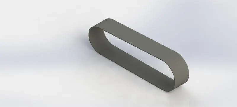
Procedure for Transmission Belt Part:
- The Transmission Belt has been sketched out according to the dimensions and is fully constrained in the plane.
- The sketch has been extruded to the desired length.
- Using the offset command, the belt thickness was taken 3.5mm.
- Fillet is applied to the edges.
- The appearance of the Belt is Changed to Matte Rubber.
Kickstand:
A kickstand is a device that allows a bicycle or motorbike to be held upright without the need of another person or an item.
A kickstand is often a piece of metal that extends from the frame and contacts the ground.
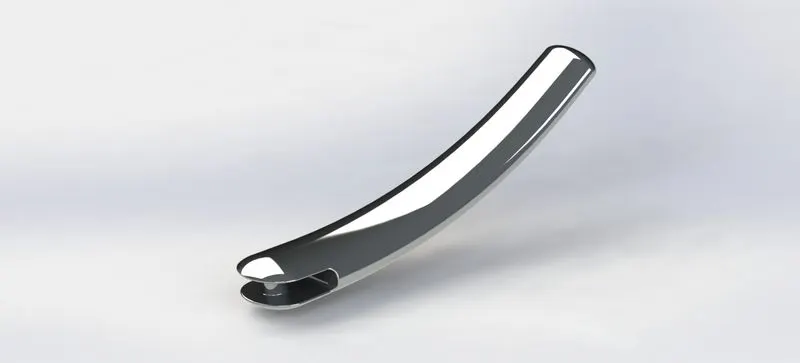
Procedure for Kickstand Part:
- The sketch is drawn with an ellipse, spline, and constrained in the respected plane, the kickstand sketch was built according to the dimensions.
- There are two ellipses formed. The top ellipse is drawn, then the other ellipses are produced in a different plane.
- The lofting command is used to create a model that connects the two sketches.
- Extrude cut was utilized to remove the undesirable portion of the component.
- A dome is utilized to make the kickstands rounded end.
Chain:
A bicycle chain is a roller chain that transmits power from the pedals to the bicycle’s drive wheel. Consequently, it is propelled. The majority of bicycle chains are constructed of ordinary carbon or alloy steel; however, some are nickel-plated for rust resistance or aesthetics.
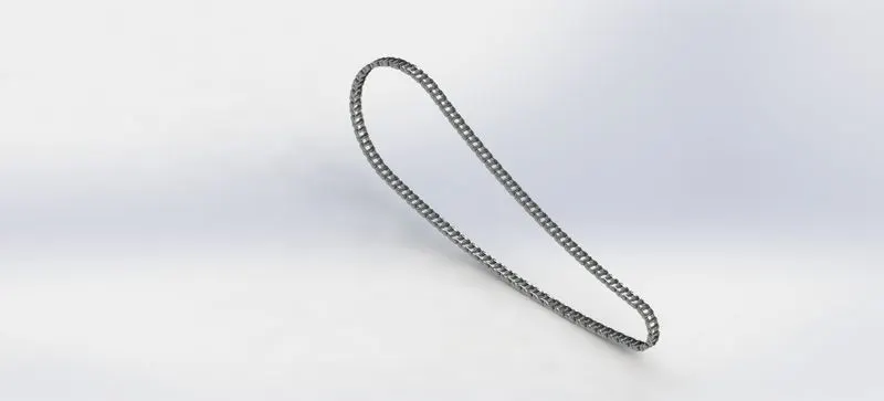
Procedure for Chain Part:
- The chain has been sketched up in 3D with 3-point arcs and tangent relation between the arcs, all while being fully constrained in the respected plane.
- Using the linear pattern and circular pattern features, draw the inner and outer plates of the chain and save them as blocks to insert anywhere we need to join.
- The constructed chain links and pins are filled on the main sketch.
- To complete the model, all of the chain links are duplicated on the other side of the plates.
- The chain has a carbon steel appearance.
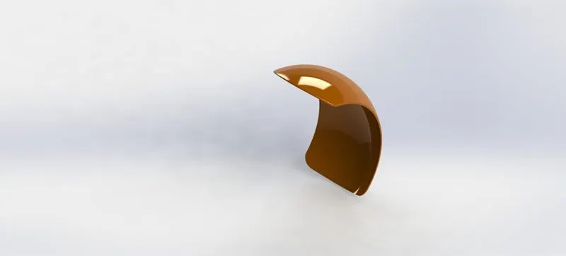
Rear Fender:
When cycling on wet roads caused by drizzle, recent rain, or snowmelt, fenders make a huge difference. Amid a torrential downpour. You may get soaked from the rain. Fenders, on the other hand, will protect your body and bike from muck and sand churned up nasty puddles and rivulets.
Procedure for Rear Fender Part:
- The drawing for the rear fender was generated utilizing three dimensions in the front plane, offset according to the thickness of the fender, and completely constrained in the respected plane.
- Make an axis at the start.
- The needed fender has been built using Revolve Boss.
- Fillets are placed at the fender’s sharp edges.
- The fender is given the required appearance.
Rear Wheel:
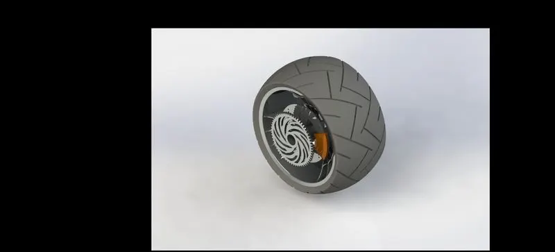
Rear-wheel is a form of engine and transmission layout used in motor vehicles, where the engine drives the rear wheels only.
Procedure for Rear Wheel Part:
There are five parts to Rear Wheel are:
- Rim: The rim is first sketched on the plane with provided dimensions and then rotated around an axis at the origin. On the plane, a spider web pattern is constructed and extruded using the midplane extrude function. The web is fashioned in a circular pattern to finish the rim. Then they were put together to make a single component.
- Rotor: Extrude the drawing on the front plane using the supplied proportions. Make holes in the extruded portion and scatter a small number of circular patterns around it.
- Caliper: Using lines and circles, create a profile of a drawing then extrude it with the midplane. Fillets and chamfers are required to finish the model.
- Sprocket: Draw a circle and extrude it to the thickness required. Create a tooth profile of extrusion and cut it with a chamfer at the edges. Fillets should be added to the model’s exterior edges. Using the circular pattern feature, make the final sprocket with the desired number of teeth.
- Tire: The ketch is made by transforming the rim’s entities and revolving the tire. The tire’s grips are then formed by creating profiles on the surface of the tire.
Pedal:
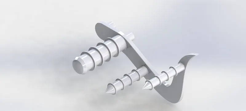
On top of that, the pedal is utilized to relax the leg. It is positioned to provide comfort to the rider. The brakes are simple to apply to the rider.
Procedure for Pedal Part:
- The drawing is created in a plane with certain dimensions and is well-defined.
- To make a model, I extruded the sketch to the desired thickness.
- Sketch the circles for the cylindrical structures for the footrest on the model’s front side, then extrude the circles.
- And create the ring surface on the cylinder by forming linear patterns.
- Apply the portion to the desired appearance.
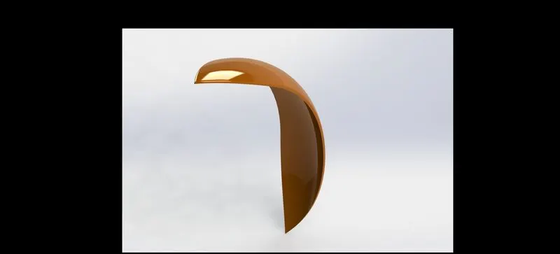
Front Fender:
When cycling on wet roads caused by drizzle, recent rain, or snowmelt, enders make a huge difference. During a heavy rainstorm, you may be drenched with pure rain falling from the sky. Fenders, on the other hand, will shield your body and bicycle from muck and sand churned up nasty piddles and rivulets.
Procedure for Front Fender:
- The required shape is drawn using the sketch tool on the required plane using their point arc and offset to create fender thickness with defined proportions.
- To draw, make an axis from the origin.
- With the help of the axis, revise the sketch. The character Fender is born.
- Draw the drawing on one end of the fender and use the split option to remove the undesirable area and achieve the desired form.
- Repeat on the opposite end of the fender to get the desired shape.
- Make fillets on the fender’s sharp edges.
- Apply the appearance of the Front Fender.
Front Wheel:
A wheel is a circular block of strong and durable material with a hole in the middle through which an axle bearing is put and around which the wheel revolves when torque is applied to its axis. One of the six simple machines might be the wheel and axle assembly.
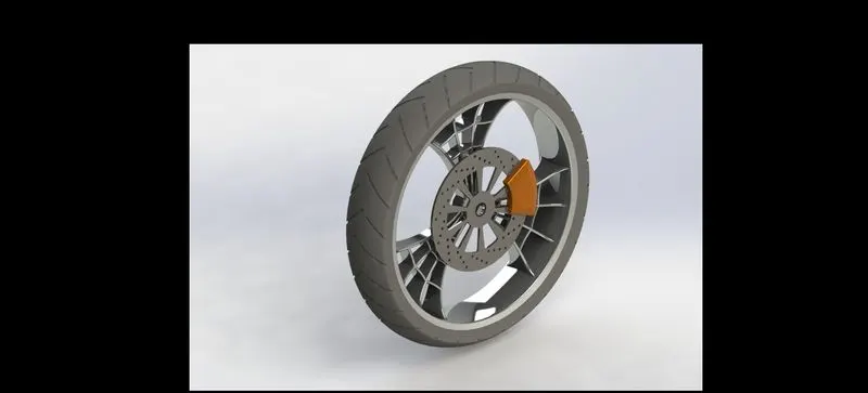
Procedure for Rear Wheel Part:
There are four parts to Rear Wheel are:
- Rim: The rim is first sketched on the plane with provided dimensions and then rotated around an axis at the origin. On the plane, a spider web pattern is constructed and extruded using the midplane extrude function. The web is fashioned in a circular pattern to finish the rim. Then they were put together to make a single component.
- Rotor: Extrude the drawing on the front plane using the supplied proportions. Make holes in the extruded portion and scatter a small number of circular patterns around it.
- Caliper: Using lines and circles, create a profile of a drawing then extrude it with the midplane. Fillets and chamfers are required to finish the model.
- Tire: The ketch is made by transforming the rim’s entities and revolving the tire. The tire’s grips are then formed by creating profiles on the surface of the tire.
Oil Tank:
The choppers oil tank is installed above the engine. The engine oil is stored in the oil tank. It’s a component of a hollow kind.
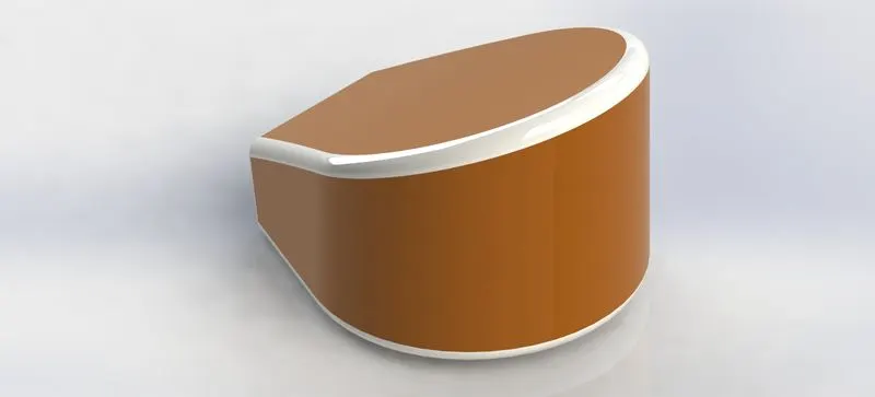
Procedure for Oil Tank part:
- The required shape is drawn using the sketch tool on the required plane using a 3 point arc and line, the tangent relation is applied to them.
- To make the component, extrude the profile.
- Using the front plane, draw a drawing and extrude it using the midplane.
- Split the bodies in half and remove the parts you don’t want.
- Fill in the needed edges with fillets.
- To construct the hallow tank in desired thickness, use the shell command.
- Finally, apply the appearance of the Oil tank.
Front Fork:
The Front Fork is made up of two long tubular parts that hold the bike’s front wheel in place. That is only one of the fork’s functions. They also move up and down, similar to an automobile shock absorber, to absorb irregularities in the road surface. The spring allows the fork leg to contact and then “spring back” after passing over a bump.
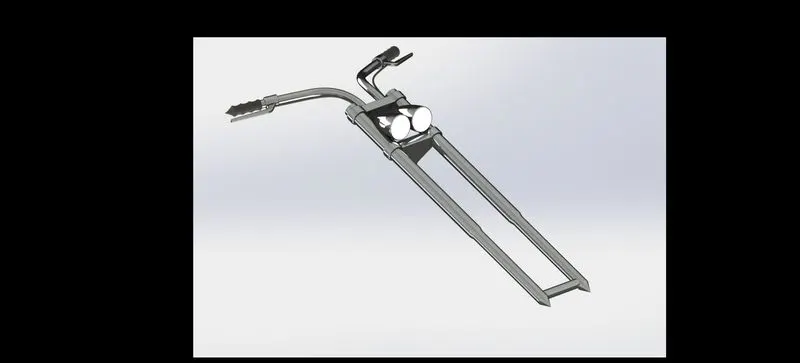
Procedure for Front Fork:
- Create a sketch of a long tube on the front plane with the required dimensions and rotate it using the axis.
- Using the command sketch, draw half of the clamp.
- Create a headlight on the same plane and rotate it to construct a component.
- Sketch the top plane and a perpendicular plane sketch to construct the project curve.
- The profile is created by drawing a circle along the curve’s boundary.
- To create the handlebar, use the swept boss and choose the profile and path.
- Select all of the bodies and use the midplane to mirror them.
- Combine all of the ingredients.
- Give the component the Appearance.
Chassis:
It is the vehicle’s backbone, on which the vehicle’s complete weight is placed. On the chassis are installed vehicle components such as the engine plant, transmission system, axels, wheels, and electrical system. It is the primary mounting point for all electrical systems that are installed on the chassis. Because it serves as the primary mounting point for all of the vehicle’s components, including the body, it is referred to as the vehicle carrying unit.
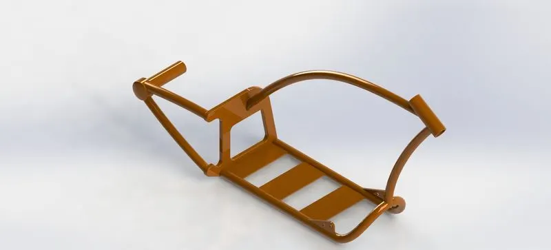
Procedure for Chassis Part:
- The chopper blueprint is imported into a component design and the placement and transparency are adjusted. The sketch of the chassis is incorporated into the blueprint plan.
- The tube’s chassis is built to the desired thickness.
- Make a sweep with the two drawings to create the project curve. For more tubes, repeat the procedures.
- Finally the tubes are attached to the panel, and the rear wheel hub of the chassis is expanded.
Engine:
Essentially, a dual exhaust system allows the engine to breathe more freely, resulting in a more complete combustion cycle. It produces more exhaust as time goes on, allowing the engine to run more efficiently an air pump, to draw more air into the engine faster, resulting in more horsepower and a more complete combustion cycle. It allows the engine, which is essentially an air pump, to get more exhaust out faster. To take more air faster, resulting in greater horsepower more exhaust means the engine, which is essentially an air pump, can work quicker. To then suck more air in quicker, resulting in horsepower. To then suck more air in faster, resulting in increased horsepower.
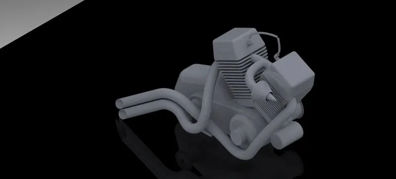
Procedure for Engine Part:
- The chopper blueprint is imported into the component design and placement and transparency are adjusted. The engine’s drawing is incorporated into the blueprint.
- A 3-point circle is used to draw the engine’s base, and lines are used to apply tangent relations.
- Extrude to the desired length and width.
- Create a plane once again and reflect the engine in a V-shape.
- Make a spline drawing and add tangent relation to them.
- the same as in another ailment.
- Use the curve tool to create a project curve and a profile on the curve for both the sketch and the profile.
- Create an exhaust tube using the sweep boss.
Fuel Gas Tank:
A Fuel tank (also known as a petrol tank) is a container for flammable liquids. That is designed to keep them safe. Through any gasoline storage tank might be named such. The phrase is most commonly used to describe the section of an engine system where fuel is stored and either pushed or discharged into the engine.
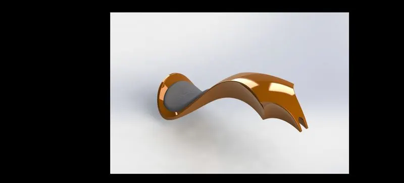
Procedure for Fuel Gas Tank:
- Using splines in the front plane. lines are projected using the constructing line.
- Make a surface sweep over half of a tank.
- Make another surface extrude to take a seat. Mirror the generated section of the tank.
- Knit the entire surface together
- Apply the desired appearance to the gasoline Tank.
ASSEMBLY OF AMERICAN CHOPPER:
- In the assembly we have chosen a bottom-up approach to building our chopper, therefore we will design each item together in an assembly section.
- The following components of our American Chopper:
- Transmission Belt
- Kickstand
- Pedal
- Front Fender
- Rear Fender
- Oil Tank
- Stand
- Chain
- Front Wheel
- Rear Wheel
- Front Fork
- Chassis
- Engine
- In Solidworks, all of the designed components are placed in the Assembly area.
- Different mating relations such as coincident, Parallel, perpendicular. The typical mates are concentric and Tangent. After all of the pieces have been joined with suitable mates, the assembly is ready to take on the appearance of a complete chopper.
- The Decals are applied in the required parts.
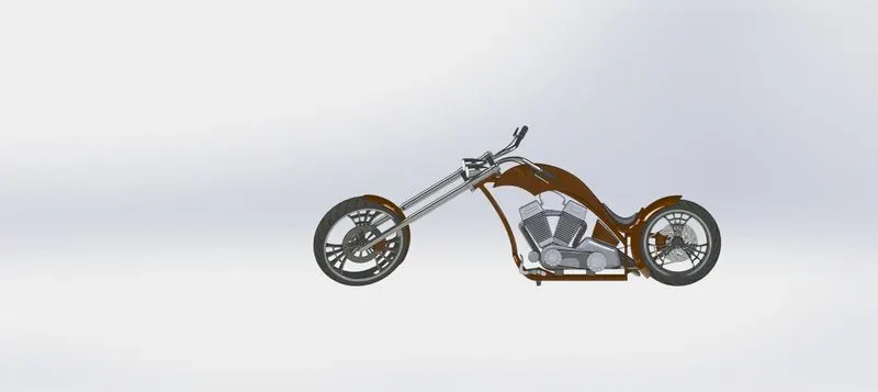
ISOMETRIC VIEW:
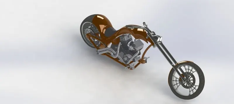
FRONT VIEW:
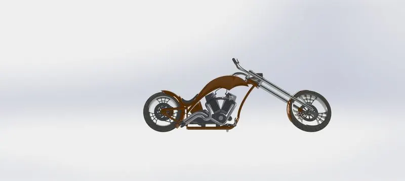
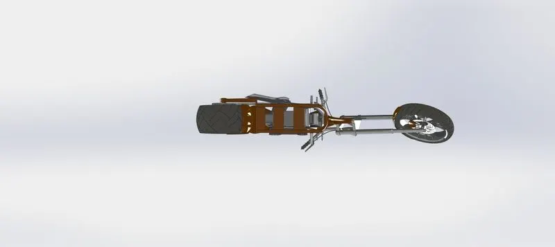
TOP VIEW:
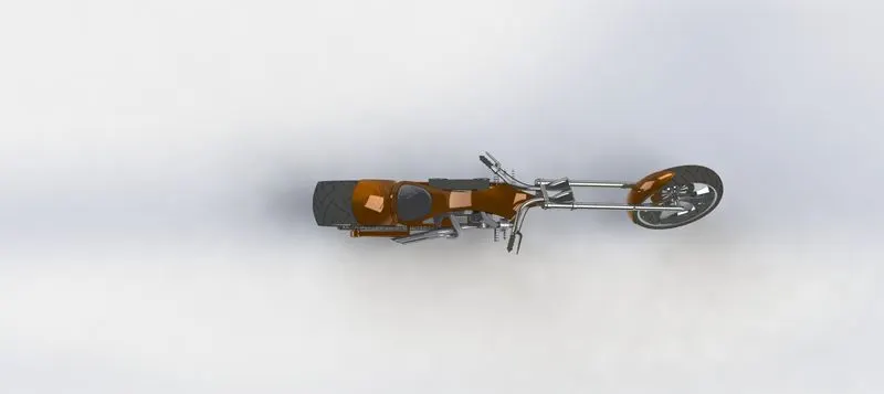
RIGHT SIDE VIEW:
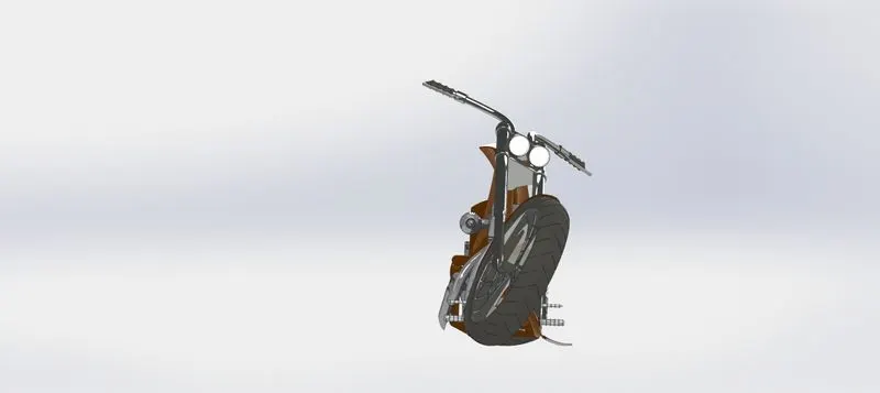
LEFT SIDE VIEW:
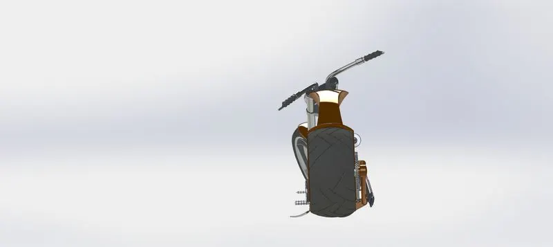
BACK SIDE VIEW:
BOTTOM VIEW:
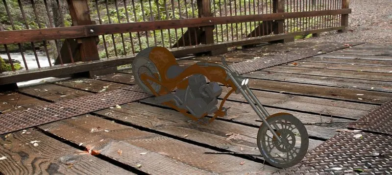
RENDERING WITH SCENE:
Conclusion:
In Chopper assembly the parts are sketched as per the dimensions using Solidworks.
All the parts are inserted in the assembled and the chopper with mating relations.
Photo view 360 was used to provide the Realistic look for the American Chopper.