Week -2
Q 1. Make a Simulink model of Doorbell using solenoid block
Door bell is daily used items and almost every house contains it perfectly. The door bell is nothing but an electrical circuit in which it has simply an electromagnet by which the hammer of the bell attracts and connect to the metal part which sounds metallic and after that the magnetism will zero the tong comes back to its ground position. This method will be done very fast and we hear the sound of the ringing bell. But here we will see the operation of the doorbell using a solenoid block.
The basic design of the doorbell is as follows.
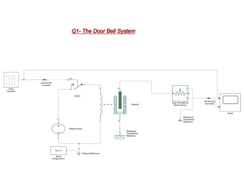
Here we can see various components are using in this model such as solenoid, a pulse generator, a switch, a voltage source, mechanical translational sensor, electrical and mechanical reference, a switch and a scope. Why those are being used and how the working principle of this model are being discussed below.
Pulse Generator: Pulse generator can generate discreate square wave pulse which provides some positive or negative pulse in a certain period of time.
Solenoid: Solenoid is an electro magnetic component. If a electricity passes through a solenoid it makes an electromagnet by which its plunger (in Fig. it represents R) moves up and down which is called a translational motion.
Ideal Translational motion Sensor: It can sense and measure of the position and velocity of any equipment which can move linearly.
Scope: Scope is such a component which makes us understand the actual characteristics of the entire system by some simple curves. We can analyse the logic through these curves.
Working Principle of the doorbell:
As per the question given, when the switch is closed the electromagnet receives electrical power from the battery and pulls the metal arm to hit the bell producing sound. But the situation is the switch is closed for 2 seconds and then released. So, we make this model which is totally satisfying the above situations. Here we are using a pulse generator by which we can create a discrete positive square wave pulse for 2 sec intervals. That means a 4 sec time period we create 2 positive pulses in the 2 seconds of interval. This pulse generator connects to the switch directly. The other port of the switch is connected to the positive side of the voltage source. The positive part of the solenoid connected to the switch and negative part of the solenoid is connected to the negative part of the switch. Since solenoid is a mechanical component so we are using mechanical reference with it. Here it is the basic model till the solenoid.
Here we find that when the voltage source connected to the solenoid and the switch is on the electromagnet will make and the plunger of the solenoid vibrate linearly. So, we need to study the position of the plunger of the solenoid. For this reason, we are using ideal translational motion sensor which can sense the position of the plunger. To study this, we are using a scope so that the position can be visible in front of use through a curve. The curve is showing as follows.
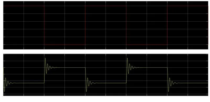
Here we can see the two plots. The very first plot shows the curve of the pulse generator. We can see that it gives a pulse of 2 seconds and then come back to zero then again it makes a value of next 2 seconds and then come to zero. The next curve is for the plunger of the solenoid. The plunger moves accordingly with the pulse generator and also, we can see a small vibration inside it. This plunger vibrates accordingly when the pulse is generated.
Now this is the basic model of a doorbell. If could we connect a hammer with the plunger and fix a metal bell near it, the hammer will hit the bell with the help of the vibration of the plunger of the solenoid and the sound will produce.
This is how the doorbell works with satisfying the above-mentioned situation.
Q2: Use a thermistor to sense the temperature of a heater & turn on or turn off the fan
We all know that thermistor is a thermal sensor in which there is a contactor which has N/O and N/C contact which latches according to some conditions. In above question we have some conditions and they are on 20 °C from 0 to 10 seconds, 27 °C from 10 to 30 seconds, 23 °C from 30 to 50 seconds and Fan conditions ON if the temperature above 25 °C, OFF otherwise. To understand this, we have made a Simulink model which is as follows.
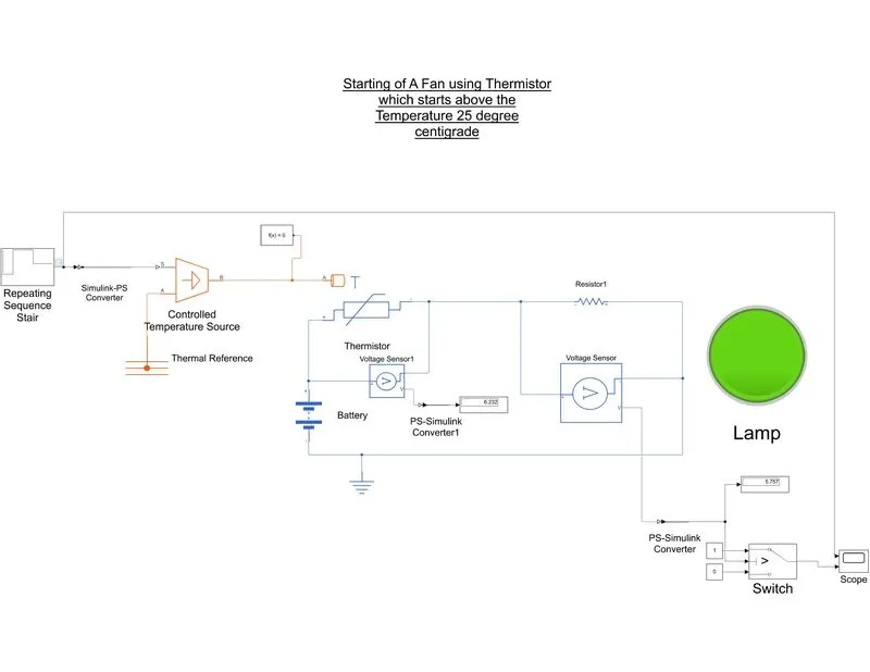
Here we are using some components such as a thermistor, controlled temperature source, 2nos. of voltage sensor, repeating sequence stair, a battery or a voltage source, a switch, a scope and a display and a lamp for the indication whether the system is actually on or not. So discussion is as below.
Repeating sequence stair: Repeating sequence stair is a component which can provide the signal according to the given condition. We have the condition that 200C from 0 sec to 10 sec, , 27 °C from 10 to 30 seconds, 23 °C from 30 to 50 seconds. So if we divide the time period for 10sec sequentially we have 200C from 0 sec to 10, , 27 °C from 10 to 20 seconds, , 27 °C from 20 to 30 seconds, 23 °C from 30 to 40 seconds and 23 °C from 40 to 50 seconds. So, we got the time mapping which has been implemented as a form in the configuration of repeating sequence stair which gives a curve that satisfies the above-mentioned condition. So, we can make any kind of signal by using this.
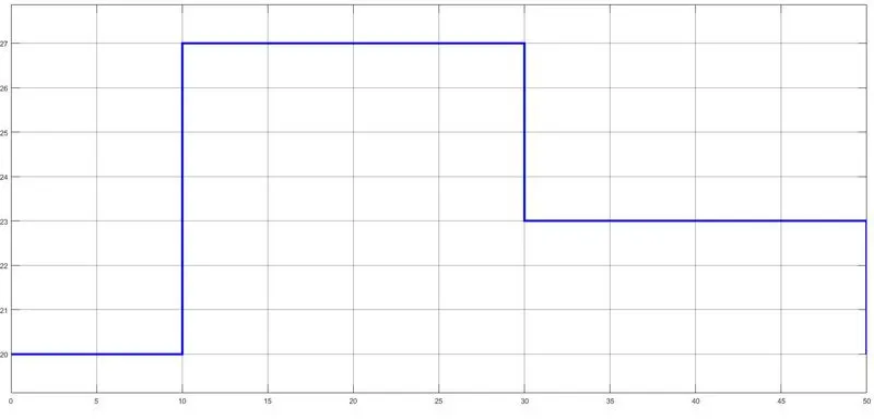
this is the input signal made my repeating signal sequence stair.
The logic has been given to the repeating signal sequence is as follows.
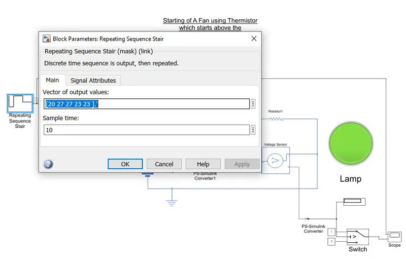
Here we give the vector of output values and the sample time is 10. We divide the entire time period into some sequence in 10 sec interval.
Controlled Temperature Source: This block represents an ideal energy source in a thermal network that can maintain a controlled temperature difference regardless of the heat flow rate. This block is connected to the repeating signal sequence and its output connect with the thermistor’s thermal input.
Thermistor: Here we are using NTC Thermistor. The thermistor contains some electrical and some thermodynamics part. The electrical part is connected to a voltage source or a battery. The thermistor has a internal resistance we set the parameter of its as follows.
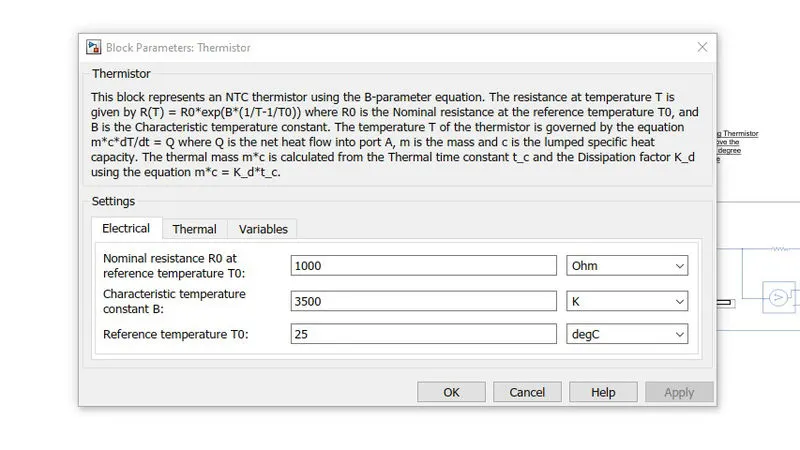
Here we set the resistance of 1000 ohm and the reference temperature is 25 degC because the fan will start above 25 degrees centigrade. Also we are using a resistance of 1000 ohm in series with the thermistor. So we have here found a voltage divider between thermistor and the connected resistor. When the voltage is applied to the thermistor the heating coil will heat and the resistance of the thermistor goes down and the connected additional resistance will be increased.
Voltage Sensor: Voltage sensor can sense the voltage drop across every resistor or component. Here we want to sense the voltage across the thermistor and the resistor. So we use the display which is connected to the voltage sensors to see the calculated voltage across those components.
Configuration of the switch: Here we are using the following switch which is as follows .
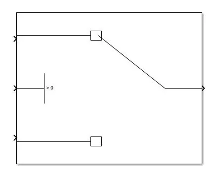
Here we can see the switch contains three inputs and one output. The middle input of the switch is threshold. The logic behind is if the input of the switch is greater than the threshold, it will give output of the value of top input. If the input value is less than the threshold then the switch gives output of the bottom input. So, with this logic we set the threshold parameter as follows.
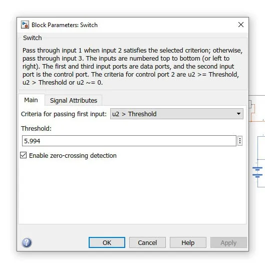
Here we input the value 5.994 which is the voltage drop across the resistor. And we connect two constants which is connected to another two inputs of the switch. The constants have been set 1 and 0 which is acting in binary model. The 1 means the switch is on and 0 means the switch is in OFF condition. Now if the volage is less than 5.994 then the switch set its logic into 0 and if the voltage is 5.994 and its above then the swich shows 1 and it will in ON condition.To display all over the characteristic system we connect a scope and also the scope is connected to the repeating sequence stair because we can compare the signals.
Observation and Conclusion: We have to simulate the system and the simulation time will be 50 sec because the total system’s time period is 50 secs. So when we simulate we have found the following curve in the scope.
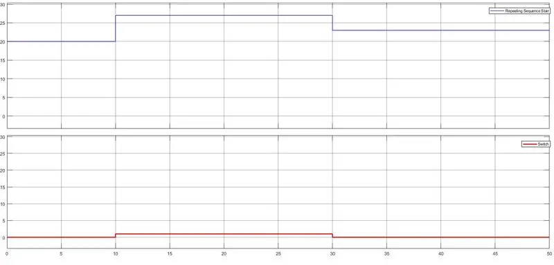
We find the curve of the sequence stair as per the above. It run 10 degree C for 0 to 10 sec and 27 degrees in next 10 to 30 sec and 23 degree in last 30 to 50 secs which satisfies the questioned circumstance. According to this we find the curve which comes from the output of the switch. We see that when the temperature reaches 25 degree the switch is on and last 30 to 50 secs since the temperature is 23 degree C, the switch is off.
If we connect a fan after the swicch the fan will work accordingly which satisfies the mentioned circumstances.
This the entire operation of the fan which controlled by using a thermistor.