Week -2
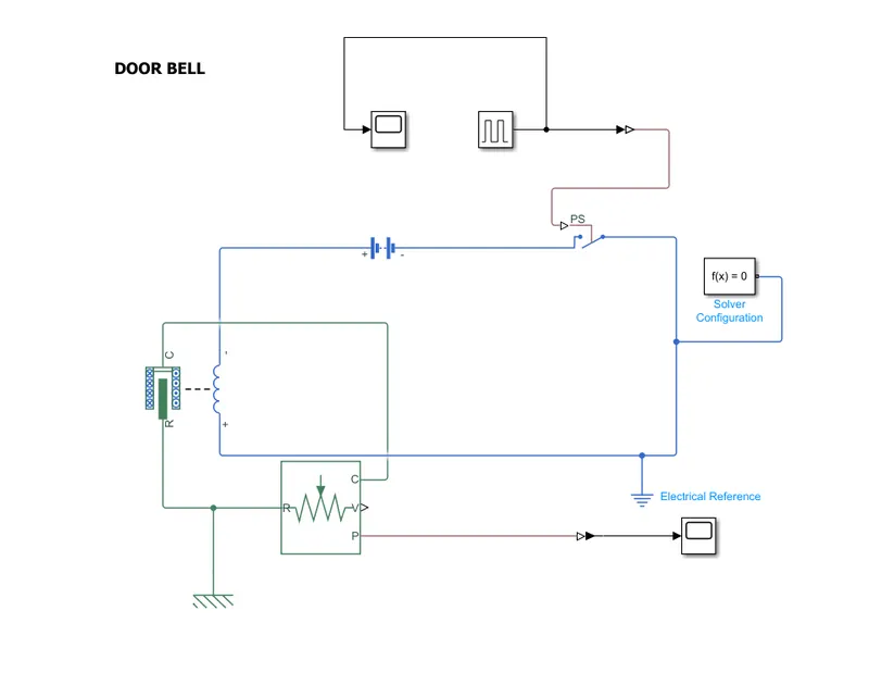
We need a solenoid ,ideal translation motion sensor ,pulse generator , a switch ,solver configuration ,a battery ,Mechanical Translation Reference ,Electrical reference. And we need two scopes for getting the plot in output and input
For getting this all easily just double click on the screen and search required blocks .
These blocks need to be arranged in the order of solenoid and battery are connected with the terminals. To control the current flow between the battery block and the solenoid block ,a switch is placed .the switch is controlled according to the threshold parameters .Then the battery ,switch and the solenoid terminals are grounded with electrical reference ,the electrical reference is connected towards the negative terminals of battery and the solenoid .The switch block is connected with the pulse generator .Then we need to change the parameters in the pulse generator of the Amplitude ,period , pulse width and Phase delay
The port R in solenoid is connected to the port R in V ideal translation motion sensor
‘V&P’ of ideal translation motion sensor are physical output port for velocity and position .The port C of solenoid is connected to the connection C of the output of ideal translation motion sensor and both the connection are connected to mechanical reference .solver configuration is connected to model
Finally run the simulation for stopping time 10 sec
Then select the scope to get the output plots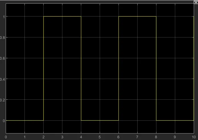
this is how we will are giving the input values and these values get by the help of the pulse generatere .when we had checked the symbol of pulse generatre block we can as same this and the output we will is
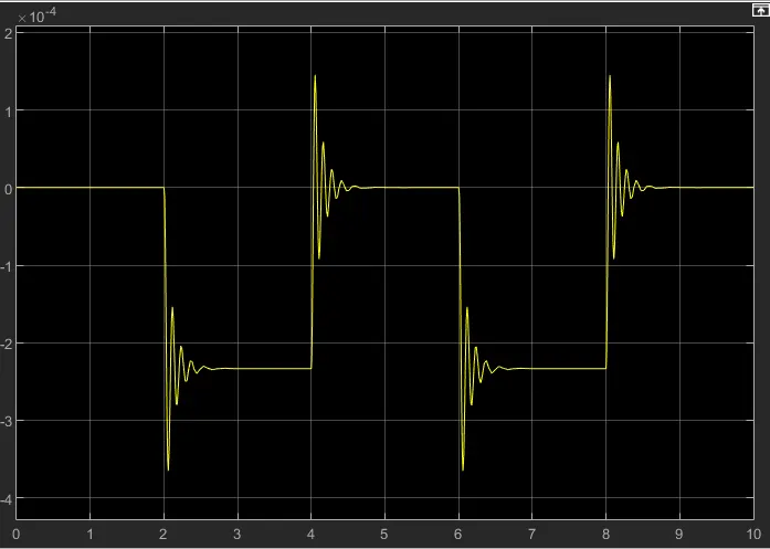
This is the output we will get and this variation comes because of the presents of solinoid and all
2.THERMISTOR
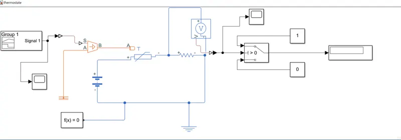
-For creating the thermostate we need a Signal Builder ,Controlled Temperature Source ,Thermistor ,Solver Configuration ,Thermal Reference ,Battery ,Resistor ,Electrical Reference ,Voltage Sensor ,Switch ,Constant ,Scope ,Display
These blocks need to be arranged in the order of first of all new need a signal block to which the scope is connected by mean of Simulink PS converter and it followed to the port S of controlled Temperature source and port A id connected to the Thermal reference. The signal from signal bilder is fed into port A of Thermistor .The positive side of thermistor is connected to positive of battery terminal and the negative side is connected to the Voltage Sensor .Then we need to change the parameter of the thermistor ,in variable window the priority level is set to Low .The negative terminal of battery and voltage sensor are grounded with Electrical reference
The port V from the sensor is connected to scope and in between PS Simulink converter also placed and it followed to the switch ,the other two terminals of switch is constants blocks are connected .The switch working under the condition of threshold value ,then switch block is connected to the display block .
Then we want to change the graph of the signal by clicking on signal block and change according to our given condition for that we need to first of all change the change in time of graph as required .Then run the programme by giving the stopping time to 50, the output plots we will get in the scope