Week -2
AIM:
- Make a Simulink model of Doorbell using solenoid block with the following details
- Use a thermistor to sense the temperature of a heater & turn on or turn off the fan as per the below conditions
PART 1
THEORY:
A solenoid is a type of electromagnet, the purpose of which is to generate a controlled magnetic feild through a coil wound into a tightly packed helix. The coil can be arranged to produce a uniform magnetic field in a volume of space when an electric current is passed through it. The term solenoid was coined in 1823 by andre-marie ampere to designate a helical coil.
In the study of electromagnetism,, a solenoid is a coil whose length is substantially greater than its diameter. The helical coil of a solenoid does not necessarily need to revolve around a straight-line axis; for example, william sturgeon's electromagnet of 1824 consisted of a solenoid bent into a horseshoe shape.
In engineering, the term may also refer to a variety of transducer devices that convert energy into linear motion. In simple terms, a solenoid converts electric energy into mechanical work. The term is also often used to refer to a solenoid valve, an integrated device containing an electromechanical solenoid which actuators either a pneumatic or hydraulic valve, or a solenoid switch, which is a specific type of relay that internally uses an electromechanical solenoid to operate an electrical switch; for example, an auto mobile starter solenoid or linear solenoid. solenoid bolts, a type of electromechanical locking mechanism, also exist. In electromagnetic technology, a solenoid is an actuator assembly with a sliding ferromagnetic plunger inside the coil. Without power, the plunger extends for part of its length outside the coil; applying power pulls the plunger into the coil. Electromagnets with fixed cores are not considered solenoids.
The term solenoid also refers to any device that converts electrical energy to mechanical energy using a solenoid. The device creates a magnetic feild from electric current, and uses the magnetic field to create linear motion.
MODEL:
EXPLANATION:
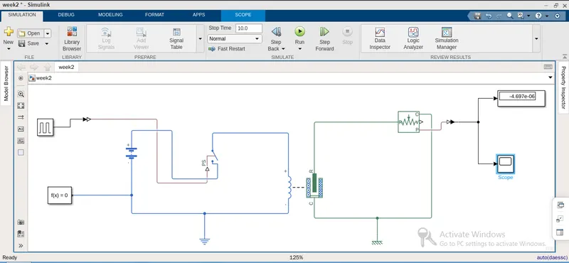
The pluse generator is connected to the switch to which the battery and solenoid is connected. The generator pluse is converted using the ps-simulink converter. Solenpoid is connected to the ideal translational motion sensor which tantamount acts as bell. From the ideal translation motion sensor the output is connected that is display, scope there the output signal is again converted using simulink to ps convertor. Battery is connected to the switch from which the solver configuration is setup to solve the equation. All the electrical components are connected electrical reference and the mechanical components to the mechanical reference.
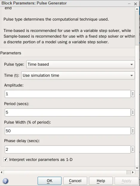
PLUSE INPUT:
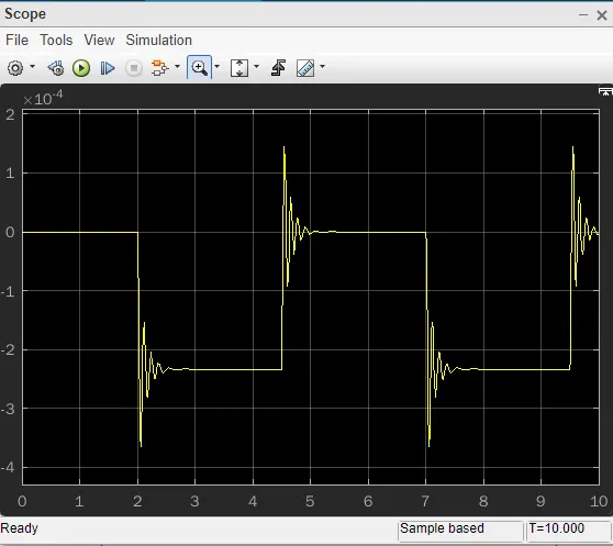
OUTPUT:
PART 2:
THEORY:
A thermistor is a resistance thermometer, or a resistor whose resistance is dependent on temperature. The term is a combination of “thermal” and “resistor”. It is made of metallic oxides, pressed into a bead, disk, or cylindrical shape and then encapsulated with an impermeable material such as epoxy or glass.
There are two types of thermistors: Negative Temperature Coefficient (NTC) and Positive Temperature Coefficient (PTC). With an NTC thermistor, when the temperature increases, resistance decreases. Conversely, when temperature decreases, resistance increases. This type of thermistor is used the most.
A PTC thermistor works a little differently. When temperature increases, the resistance increases, and when temperature decreases, resistance decreases. This type of thermistor is generally used as a fuse.
Typically, a thermistor achieves high precision within a limited temperature range of about 50ºC around the target temperature. This range is dependent on the base resistance.
MODEL:
EXPLANATION:
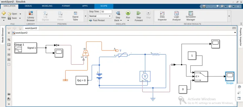
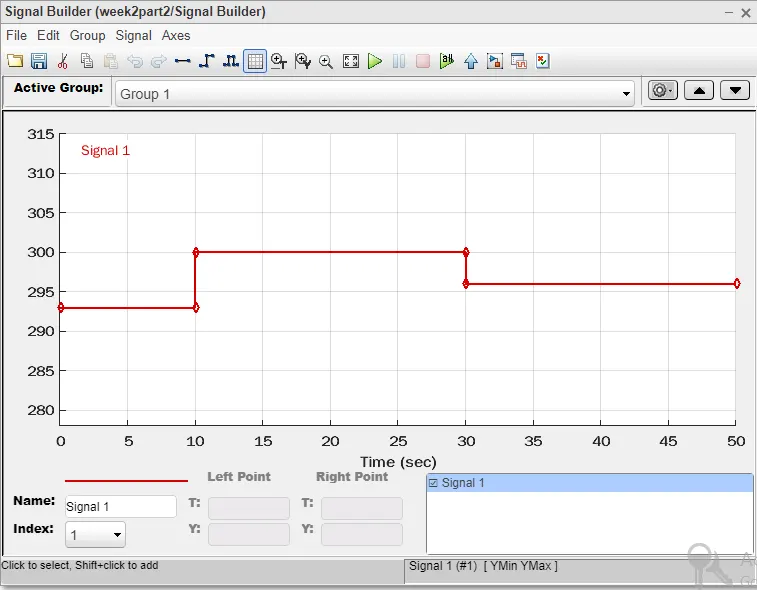
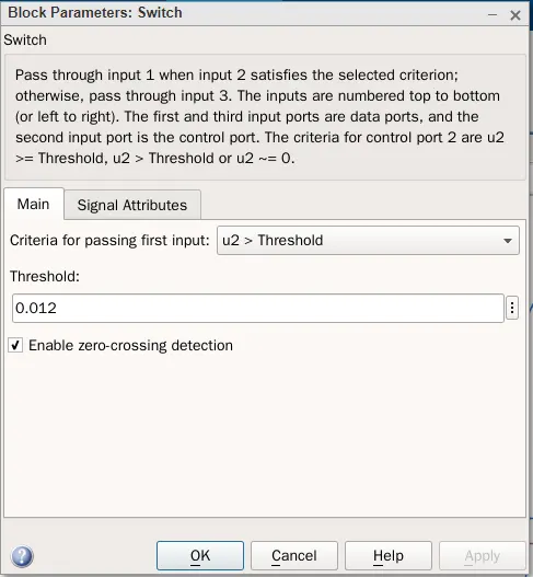
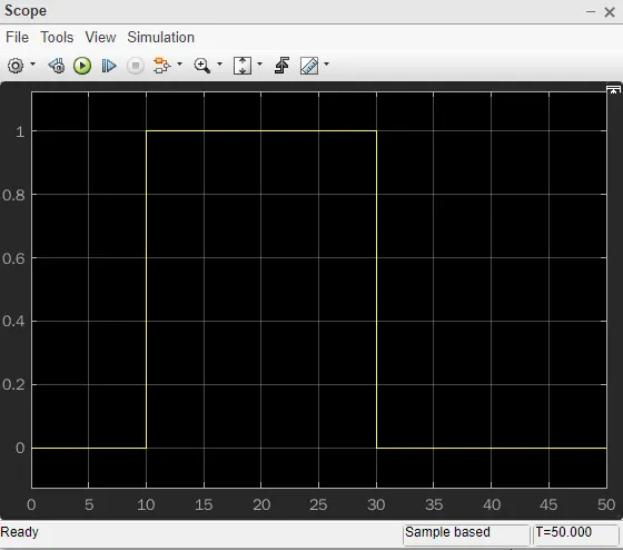
The signal input is given through the signal builder which helps to create the input signal. The input signal is then converted into the ps signal using the ps convertor through which the signals are sent to the temperature controller. From the controller the thermistor is connected through which the resistance is offered. This thermistor is connected to battery and the voltage controller to which the switch is connected. The ON condition to the switch is given with 0.12 threshold below which the switch is in OFF condition. The scope is connected at the end to get the output. The temperature reference is taken from the temperature controller out. The electrical reference is taken from the battery to resistance connection.
INPUT SIGNAL:
OUTPUT THRESHOLD:
OUTPUT:
CONCLUSION:
Thus the required plots are obtained for both the simulink blocks in accordance to the given conditions.