ELECTRIC BELL AND THERMISTOR CONTROLLED FAN SIMULATION
1.ELECTRIC BELL SIMULATION
AIM:
The aim is to develop a model that represents the electric bell working and to make the bell rings for two second .
ELECTRIC BELL WORKING:
The components in the electric bell are, battery- Which is the power supply for the whole apparatus,
Switch -It is the circuit breaker which decides whether the bell want to ring or not, Electromagnetic setup with the striker - When the current pass through this electromagnet it creates magnetic field which attracts the striker gong- It is a ball like structure made of metal, when the striker hits it ,produces ting- tong sound.
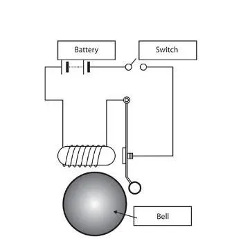
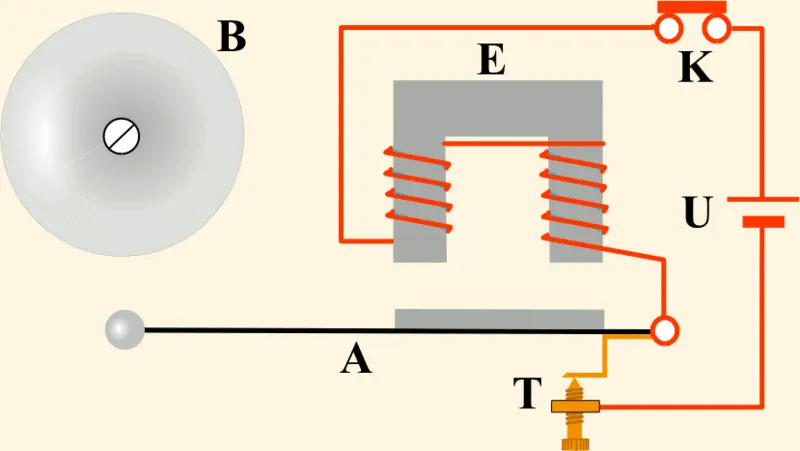
When the switch (usually push button) is pressed it completes the above circuit,then the current starts to flow in the circuit.As soon as current passes,the electromagnet generates the magnetic field surrounding it.The magnetic field attracts the striker .The attracted striker hits the gong .That's it the bell rings . When the striker is attracted the circuit breaks then the magnetic field gets reduced, followed by the striker returns to its position.This continues the user releases the switch.
The following animation describes the electric bell working.
ELECTRIC BELL IN SIMULINK:
The condition for simulation is that ,the bell should ring for 2sec and then remain idle .
In order to get that we have to use a alternating signal with time period of 2 seconds.
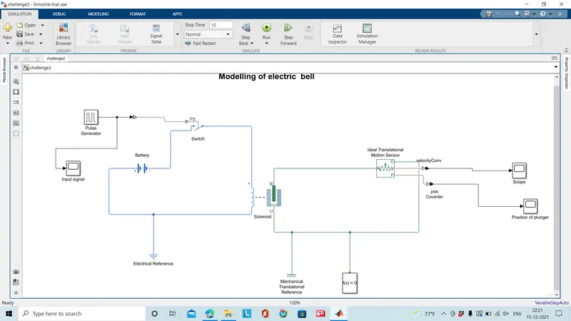
Here we use solenoid as electromagnet and the plunger in the solenoid as striker.The gong will not be present here.The blocks used in the simulink for electric bell simulations are,
Pulse generator - This creates alternating signal for the switch.
Battery- Power supply for the electric bell working.
Switch - Electrical switch for completing as well as breaking the circuit.
Solenoid- It acts as electromagnet thus on passing current it creates magnetic field and makes the plunger move.
Ideal translation motion sensor - This helps in sensing and calculating the movement and velocity of plunger in the solenoid
converter - The converter may be of simulink to physical signal or vice-versa.
Scope- To plot the desired result .
SIMULINK MODEL:
INPUT:
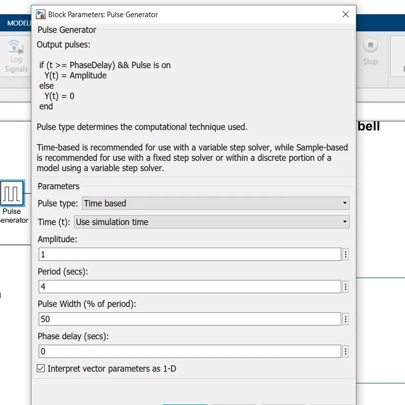
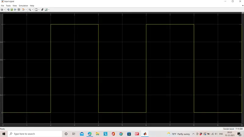
The input of the switch is a pulsating signal generated by pulse generator where the time period will be 4 secs and the phase width will be 50% ,so the period will be half.The input signal will be,
OUTPUT:
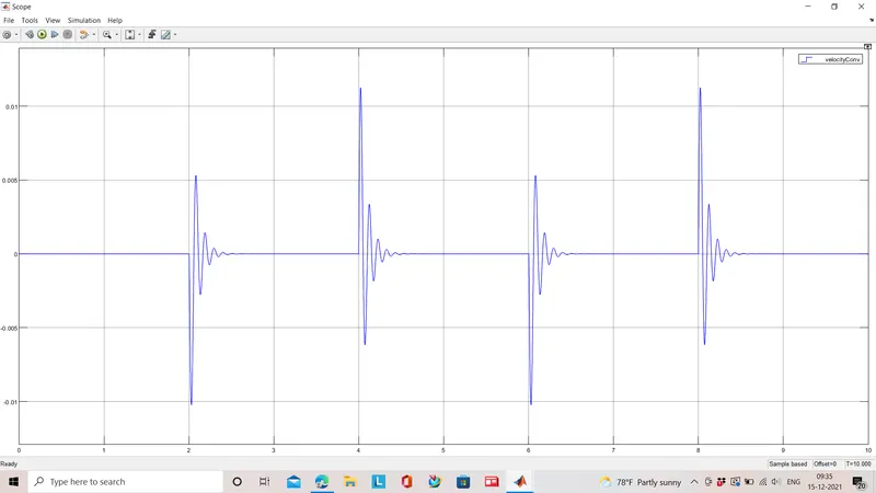
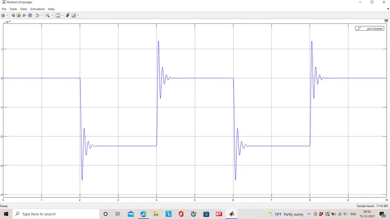
The output are shown by the scope block which depicts the velocity and displacement of the plunger will be,
The displacement of the plunger in the solenoid,it shows the plunger moves in a time period of 2 secs .It starts at 2 sec and goes on and hits the bell at 4 sec and there produces a vibration there and comes to its initial position.This process contiinues till 10 seconds.
2.THERMISTOR CONTROLLED FAN SIMULATION
AIM: The aim of this project is to create a model where the fan on and off operation is controlled by the thermistor for different temperatures.
INTRODUCTION TO THERMISTOR:
A thermistor is a device used to control the resistance of the circuit which is driven by the temperature source.It is a thermal resistor operated by temperature.It is used in temperature sensing ,controlling and measuring applications.
There are classifications in thermistor as stated below,
On increasing temperature if the resistance decreases it is Negative Temperature Coefficien(NTC) thermistor.
In the other case i.e the resistance increases on temperature rise it is Positive Temperature Coeffecient(PTC) termistor.
The NTC and PTC thermistors are manufactured in different methods and materials.The particle size and materials are to be considered while manufacturing.
Each and every thermistor has different characteristics(Thermal time constant is a chracter which is the response time of thermistor) choose the thermistor which actually fits in your model
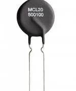
A thermistor(ptc) would look like,
CONDITION FOR MODELLING:
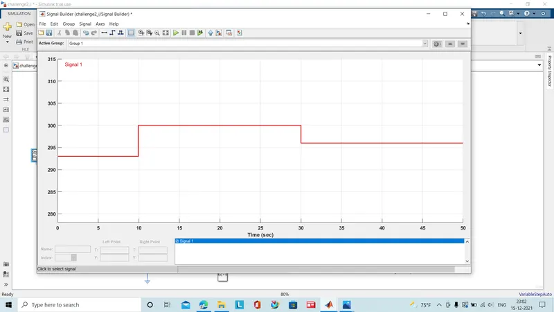
The fan should be operated when the temperature exceeds or equals 25 degree celcius unless it is switched off
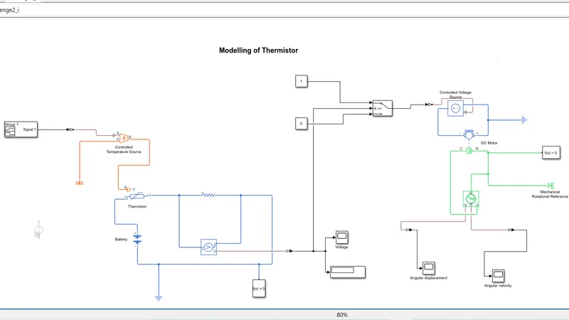
SIMULINK MODEL:
BLOCKS USED & ITS WORKING:
Signal builder: Used to feed a signal on the given condition of temperature.Note that temperature should be in kelvin (since the temperature source and thermistor operates in kelvin)
Controlled temperature source: Based on the signal provided it creates a controlled temperature difference at port B.
Thermal reference: It gives the initial condition to the temperature operated blocks with absolute zero temperature.
Battery: A power supply is provided which may be dc voltage source or a battery to operates the thermistor.
Thermistor: It performs the thermistor operation with the temperature input from the controlled temperature source.
Resistor: The resistor is connected to thermistor where the changes in resistance can be viewed from the voltage sensor block which is connected in parallel circuit.
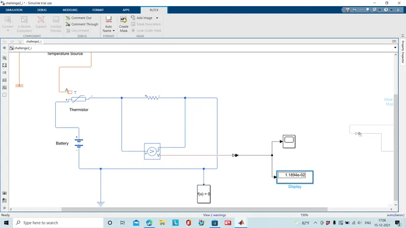
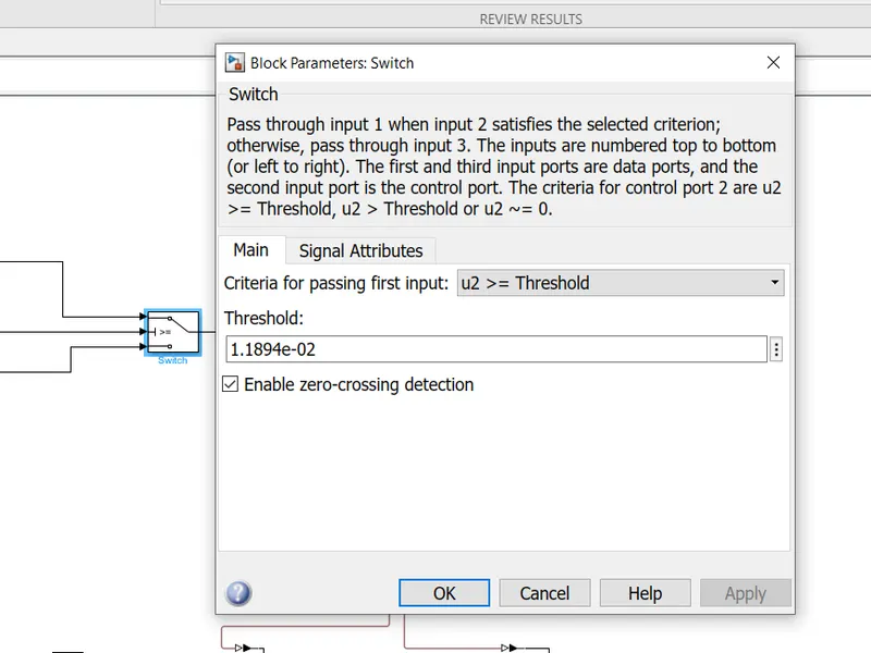
Switch: This switch has three ports , the port 2 checks the condition ,if it satisfies the it follows port 1 and orelse it follows port 3 . It's a signal routing switch . The threshold limit for the port 2 check condition is the voltage sensed on temperature input of 25 deg. celcius. The value in the display block is the threshold value.
DC motor: This is used in the place of fan in modelling.The dc motor needs a power supply ,it is feed by the controlled voltage source block.
Ideal rotational motion sensor: The movement of the dc motor is sensed by this block having R and C as input conserving ports ,the angular displacement and the velocity are measured.
Electrical reference block: A model with electrical block must contain this reference port it implies the electrical ground.
Mechanical Rotational reference:It represents frame or ground where the mechanical rotational blocks are mounted.
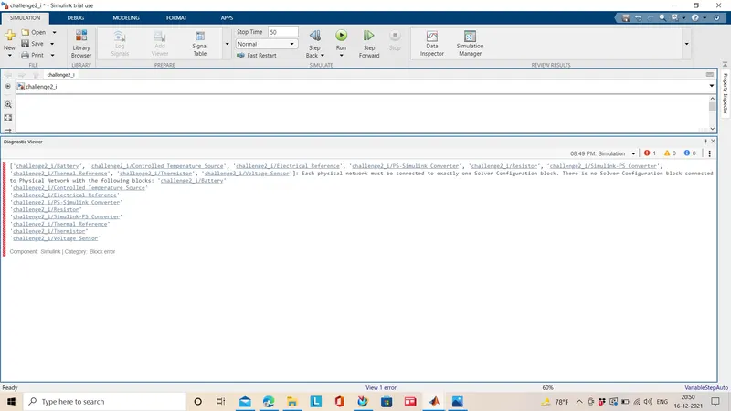
Solver configuration: The solver configuration model is essential for all simscape models .It sets up the solver setting for simulation.
Scope: It displays the provided input in graphical representation.
INPUT:
The input that is generated in the signal builder which satisfy the given condition.
OUTPUT:
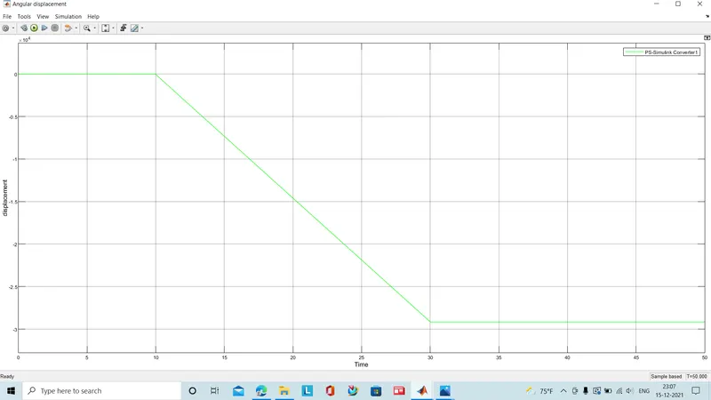
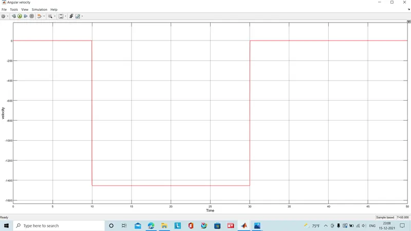
The angular displacement and the angular velocity of the fan(dc motor) when switched on(i.e the temperature exceed the 25 deg celcius) is shown below.It shows that the fan(motor) has a displacement between 10-30 sec only.
CONCLUSION:
1. The electric bell is modelled and simulated,the condition of operating for 2 seconds is achieved and plotted successfully.
2. The thermistor controlled fan was modelled and simulated as per the given instruction successfully using the simulink .
Errors faced:
If solver configuration is not used,
References:
engineeringtutorial.com_electric-bell-animation.gif (800×451)
THERMISTOR CHALLENGE : Skill-Lync
https://www.mathworks.com/help/releases/R2021b/simulink/index.