Week -2
EXPLANATION:
AIM:
1. To make a simulink model of a doorbell using solenoid block.
2. To use a thermistor to sense the temperature of a heater & turn on or turn off the fan.
1. DOORBELL:
SIMULINK MODEL
INPUT:
OUTPUT:
Pulse Generator:
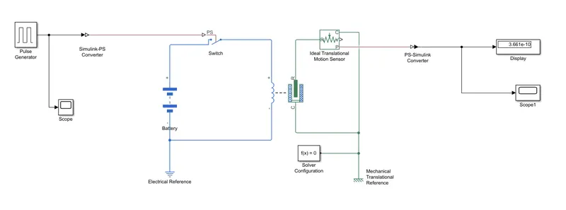
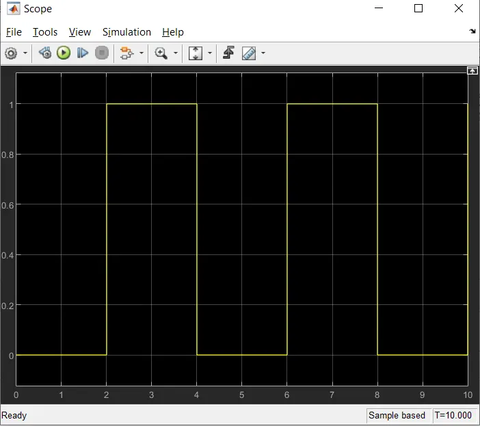
The pulse generator block generates square wave pulses at regular intervals pulse generated from PG
is converted to simulink to physical signal and given to switch for perform switch function.
Switch:
To complete this connection.
Battery:
It gives a supply for the solenoid.
Solenoid:
The solenoid blocks represents the electric characteristics and then generated a force.
Ideal Translation Motion Sensor:
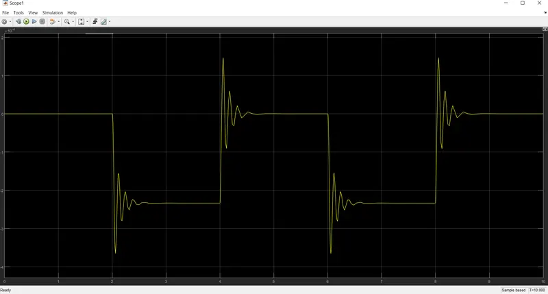
It is connected with solenoid block R to observe the movement of the plunger.
Scope:
It is connected with ideal translational motion sensor to get the output.
Solver Configuration:
Each physical network represented by a connected simscapes block requires solver setting information for
simulation.
2.THERMISTOR:
Given Condition:
1.Temperature Source: 20 Deg C from 0-10, 27 Deg C from 10-30, 23 Deg C from 30-50.
2. Fans Condition: ON if the temperature above 25 Deg C, OFF otherwise.
MODEL:
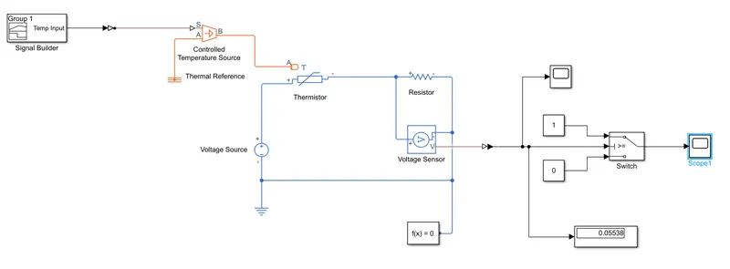
Signal Builder:
As per the given condition for temperature & time. These values are provide as inputs to the Signal Builder &
figured it as per our condition.
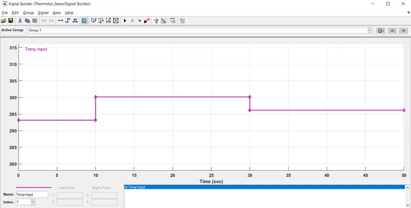
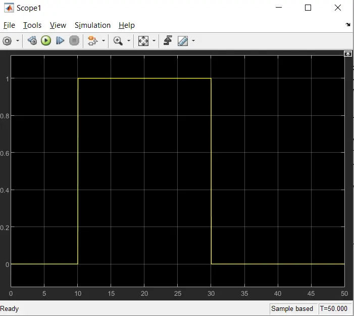
Given Inputs:
At Point-1 - Time is 0 sec - Temperature is 293K.
At Point-2 - Time is 10 sec - Temperature is 293K.
At Point-3 - Time is 10 sec - Temperature is 300K.
At Point-4 - Time is 30 sec - Temperature is 300K.
At Point-5 - Time is 30 sec - Temperature is 296K.
At Point-6 - Time is 50 sec - Temperature is 296K.
Controlled Temperature Source:
The block represents an ideal source of thermal energy that powerful is enough to maintain a specified
temperature difference across the source regardless of a heat flow consumed by the system.
Thermistor:
It is a type of resistor whose resistance depends upon temperature, dependent on temperature. This thermistor
word is a combination of thermal & resistor.
DC Voltage Source:
It imlpements the voltage source with DC/AC & noise components.
Resistor:
This is the linear resistor, described with the following equation.
V = IR
Where
V - Voltage
I - Current
R - Resistance
Voltage Sensor:
This device is convert the voltage measured between two points of an electrical circuit into physical signals is
proportional to the voltage.
Switch:
To fulfill our fan condition we add a switch & provide the threshold value this will work as like if, else, loop to give
the condition as right or wrong we add constant blocks.
The switch block is connected to scope it gives a results.
OUTPUT: