Week -2
1.
aim :
to create a simulink model of doorbell using a solenoid block, battery ,plunger and an electrical switch and to create the situation where the switch will be closed for 2 sec and then released
working of a door bell:
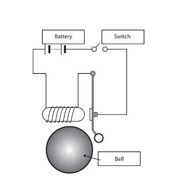
the above figure represents the door bell which consists of battery ,switch,mechanical plunger ,solenoid and bell
solenoid: a solenoid is a device comprised of a coil of wire ,the housing and a movable plunger known as armature.when electrical current flows through this coil(wire) ,a strong magnetic flux is generated. this housing is usually made of cast iron or steel,surrounds the coil concentrating the magnetic feild generated by the coil.
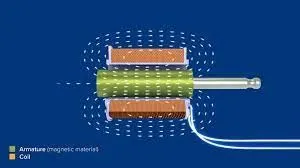
working of the door bell using the solenoid is a simple mechanisam a battery having both positive and negative terminal is taken and negative terminal of the battery is connected to the negative terminal of the solenoid ,the positve teminal is connected on end of the switch other end of the switch is connected to positve teminal of solenoid ,then take a metal arm in still position due to spring action taking place as shown the figure. due to the plunger movement of the when the current passed through the solenoid reciprocating movement of plunger guides the metal arm to provide the sound.
simulink block diagram:
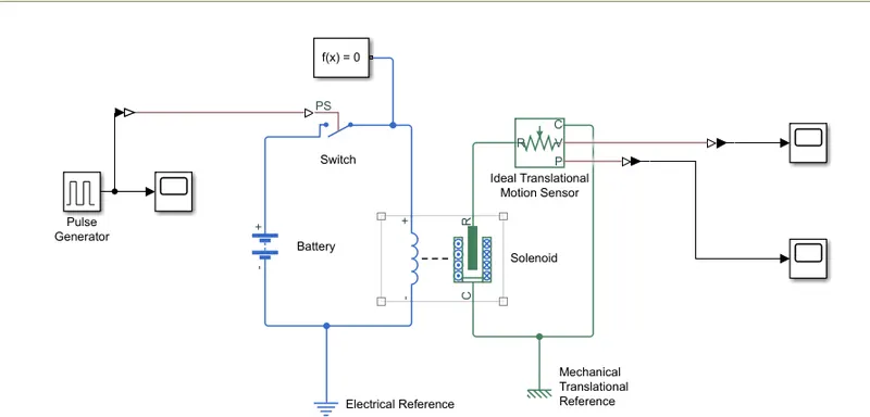
explanation of simulink block :
solenoid consists 4 signel ports in which 2 port are connected to battery and 1 port is case port and other is mechanical plunger port ,this plunger port is connected to the translational motion sensor to get the v and p signels which are namely velocity and position of the inputs, these pulses are generated by the pluse generator which controls the switch which is a external pulse controlled switch
results:
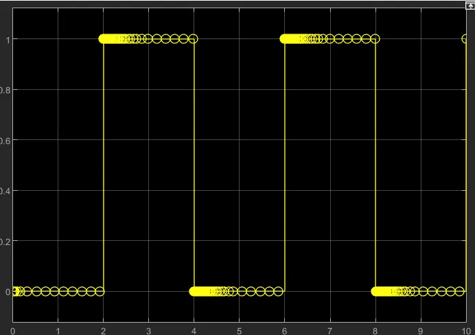
input pulse signels: these are input signels provided by the pulse generator by taking in to consideration that switch remains closed for 2 sec an then released
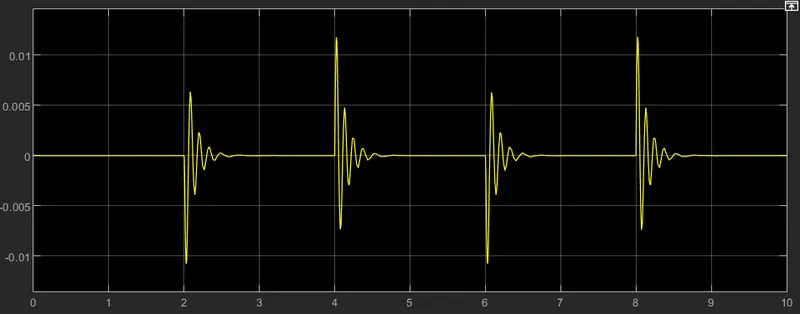
velocity signel of the plunger:
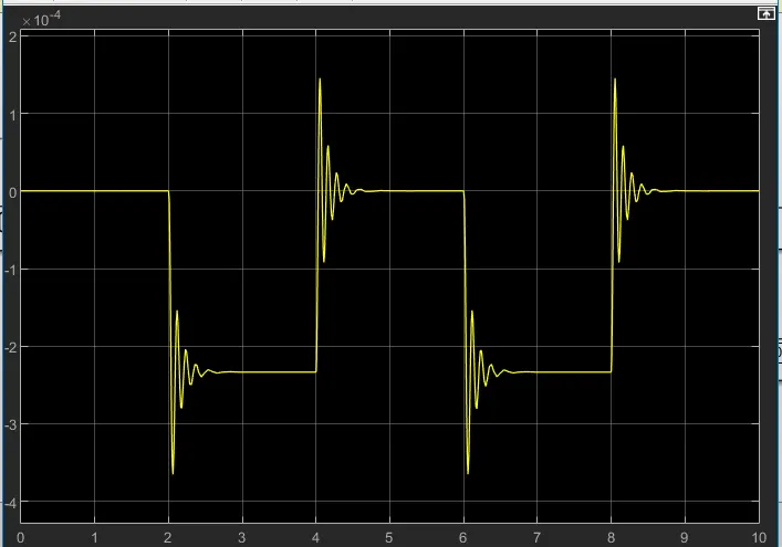
position signel of plunger:
conclusion:
the simulink project of doorbell using the solenoid is a key model of working of solenoid which converts the electrical signels in to the magnetic signels there by providing the reciprocating motion of the metal arm.using ideal translational motion sensor we can observe the behaviour of the velocity and position of the plunger which is by using the scope block
2.
aim:
a simple dc fan controller using the thermister to sence the temperature and also to turn off and on fan according to the given conditions
working simple dc fan controller:
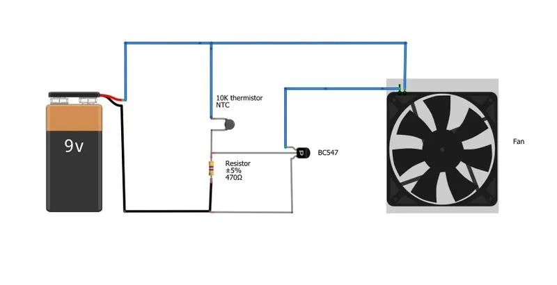
a dc fan controller is a simple mechanisam as shown in the above figure
the main components of the mechanisam are battery ,thermister,resistor and voltage sensor
the battery and the thermister are connected as shown in the figure and the resistor is in series with the thermistor a voltage sensor is in series with the resistor to calculate the voltage across the resistor according to the rise or fall in temperature in the thermistor there is a alterante increase the the voltage we fix the theshold limit of the voltage if the voltage exceeds the threshold limit fan automatically stopped
thermistor:
thermistor is made of semiconducting materials .this can be made in the form of discs,bars or grains
thermistor is a type of resistor whose value is effected by the temperature,there are mainly two types of thermistors ,which are
1.NTC
2.PTC
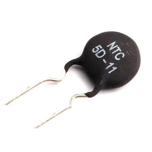
NTC thermistor:
the thermistor has resistance whose value will become samller with increasing temperature ,thermistor type is called negative temperature cofficient thermistor
NTC themistor gets smaller value with increasing the temperature
PTC thermistor:
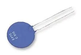
there is also a thermistor having the resistance value will be further enlarged with increasing temperature .thermistor type is called positive temperature cofficient thermistor or PTC
PTC thermistors gets greater resistance value with increasing temperature
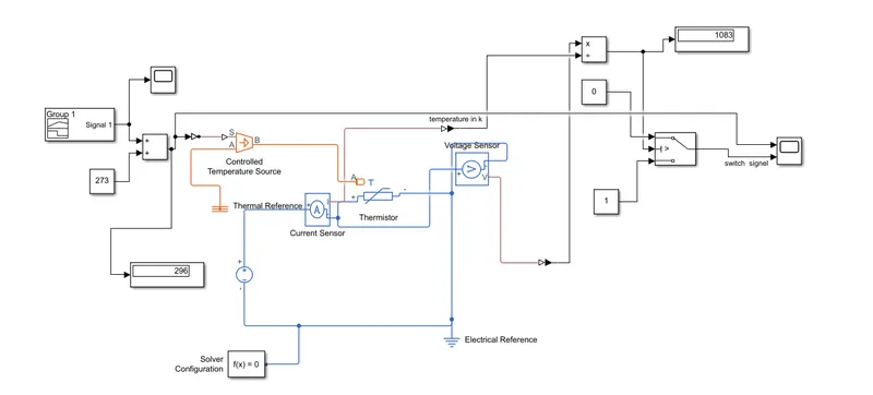
simulink block diagram:
basic components used in simulink model:
thermistor:
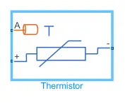
a thermistor in simulink consists of three port out of which two are connected to battery ends the remaining A port is connected to temperature source
controlled temperature source:
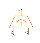 this controlled temperature source also consists of three port B port is connected to the thermister,s port is connected to the input signel and atlast A port is connected to the thermal referance
signel builder block:
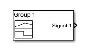
this block main purpose is to generate signel so as per the requirements of the project this consist the single output port
switch:
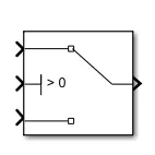
a switch consist of a three input ports out of which one port is input signel port ports 1 and 3 are constant ports which compare the values with the 2 port
voltage source:
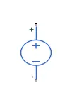
it consists of two ports positive and negative which are connected to thermistor
conditions:
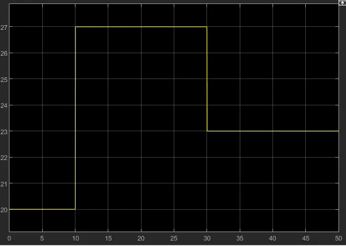
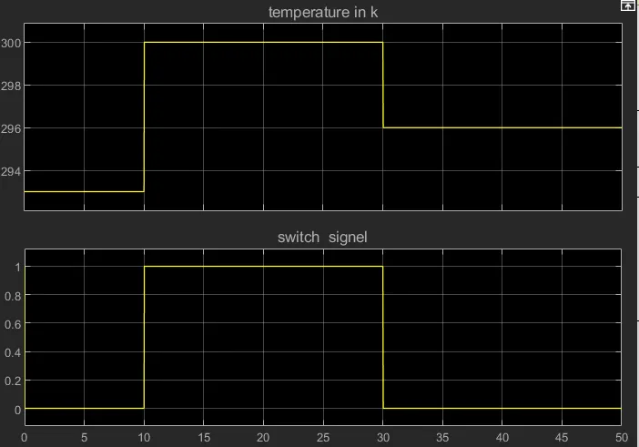
from point 1-2 temp:20 degrees time:0-10 sec
from point 3-4 temp:27 degrees time:10-30 sec
from point 5-6 temp:23 degrees time:30-50 sec
working of the simulink block:
1.from the signel builder input signel is passed through the using ps - converter and connected to s port of controlled temperature source
2.then from a controlled temperature source B port it is connected to the A port of the thermistor other two treminals are connected to the positive and negative terminals of a battery with a resistor between them
3.a voltage sensor is connected in parallel with resistor an also a ammeter sensor in parallel with the thermistor
4 .the two signels from the ammeter and voltage sources are converted using the ps-converter and according to the ohm's law they are divided to get a resistance value this value is given to the switch
5.a threashold value of resistance is given to the switch according to the input values it stimulates value between the two constant connects the suitable connection
6.by using the thermistor we can get the different values of resistances based on the input temperatures by using the values of resistances we can controll the switch of fan on/off.
results:
input signel:
output signal:
conclusion:
thermsiter is a device which have different values of temperature for every temperature using this concept of thermister a simple dc fan controller is built if the temperature is above 25 degrees then corresponding resistance values changes .if it exceeds the threshold value then it automatically off.