Week -2
1. Make a Simulink model of Doorbell using solenoid block.
Aim: To make a Simulink model of Doorbell using solenoid block
Simulink model:
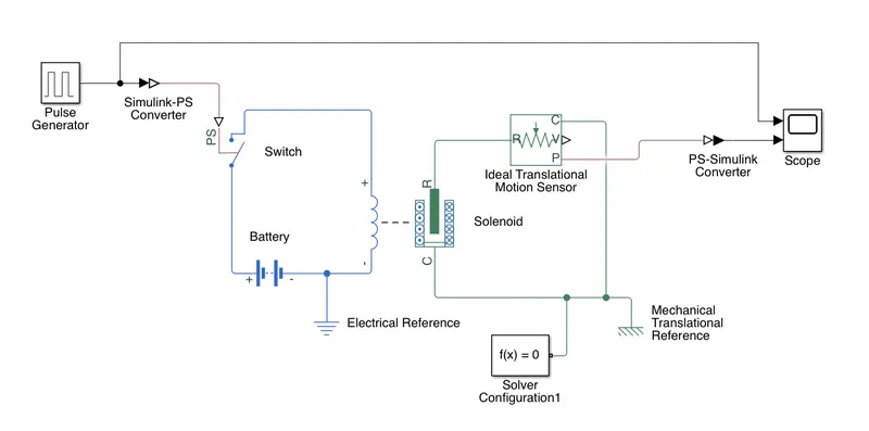
In the above arrangement, when the switch is closed the electromagnet receives electrical power from the battery and pulls the metal arm to hit the bell producing sound.
Blocks used:
1.Pulse generator is used to close the switch for 2 seconds and then released. Two cycles are generated for closing the switch twice for 2sec.
2.Simulink-PS Converter is used to convert the simulink signal to physical signal for operation of the switch.
3.Switch-Battery-Solenoid are connected in series so that when the switch is closed, the solenoid get energised and attract the plunger and bell rings.
4.Ideal Translational motion sensor is used to sense the plunger movement.
5.PS-Simulink converter is used to convert the output of Ideal Translational motion sensor to Simulink signal and the output is displayed in using Scope along with Pulse generator signal.
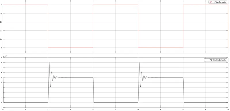
Output of the Simulation:
Results:
From the above graph it is observed that when the switch is closed for the first 2 seconds the plunger is moved from position 5 mm to 0 mm and once the signal is OFF after 2 seconds the plunger is moved back to its original position with some transient movement.
2. Use a thermistor to sense the temperature of a heater & turn on or turn off the fan.
Aim: Turn ON/OFF the fan using thermistor
Simulink model:
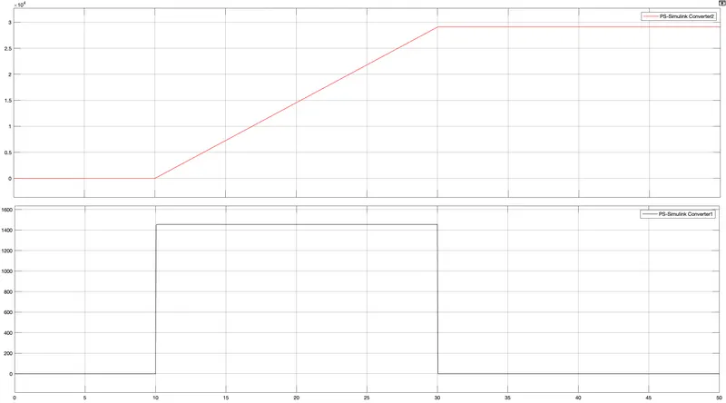
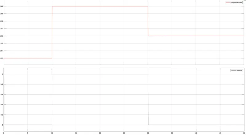
Temperature source: 20 °C from 0 to 10 seconds, 27 °C from 10 to 30 seconds, 23 °C from 30 to 50 seconds
Fan conditions: ON if the temperature above 25 °C, OFF otherwise
Blocks used:
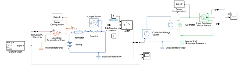
- Signal Builder block is used to generate 20 °C from 0 to 10 seconds, 27 °C from 10 to 30 seconds, 23 °C from 30 to 50 seconds.
- Simulink-PS Converter is used to convert Signal from Signal Builder to physical signal.
- Output of Simulink-PS Converter is connected to Controlled temperature Source.
- Controlled temperature Source output is connected to thermistor.
- Thermister-Battery-Resistor is connected in series and voltage is measured across resistor using voltage sensor.
- Output of Voltage sensor is connected to Switch with a threshold value of 0.01196 (corresponding to 25 °C). If the output of voltage sensor is more than the threshold value, the output of switch will be ‘1’ and if output of voltage sensor is less than threshold value, output of switch will be ‘0’.
- Switch output is monitored using scope and same is given to controlled voltage source which is connected to DC motor for ON/OFF control of fan. Fan will be ON if the temperature is more than 25 °C and OFF if the temperature is less than 25 °C.
- Ideal Rotational Motion sensor is used to sense the angular velocity and angle of the Motor. The output of motion sensor is connected to scope to monitor the angular velocity and angle of the fan motor.
Simulation result:
The plot of Signal Builder and Switch Output which shows 20 °C from 0 to 10 seconds, 27 °C from 10 to 30 seconds, 23 °C from 30 to 50 seconds and Fan ON if the temperature above 25 °C, OFF otherwise
The plot showing output of Ideal Rotational Motion sensor