Week-6 Challenge: EV Drivetrain
1. Which types of power converter circuits are employed in electric and hybrid electric vehicle?
There are three types of Power Converter circuits employed in Electric and Hybrid Electric vehicles, namely
-
AC-DC Converter/Rectifier
-
DC-AC Inverter
-
DC-DC Chopper
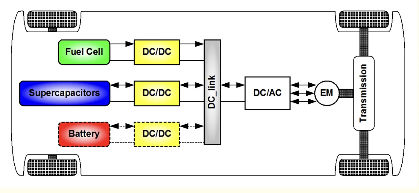
DC-AC Inverter
An inverter is a device that converts DC power to the AC power used in an electric vehicle motor. The inverter can change the speed at which the motor rotates by adjusting the frequency of the alternating current. It can also increase or decrease the power or torque of the motor by adjusting the amplitude of the signal.
Broadly speaking, an inverter is an electrical device that converts electricity derived from a DC (Direct Current) source to AC (Alternating Current) of the type that can be used to drive a device or appliance. In a solar power system, for example, the power stored by batteries charged by solar panels is converted to standard AC power by the inverter,1 which provides the power to plug-in outlets and other standard 120-volt devices
An inverter serves the same kind of function in a hybrid or EV car, and the theory of operation is relatively simple.2 DC power, from a hybrid battery, for example, is fed to the primary winding in a transformer within the inverter housing. Through an electronic switch (generally a set of semiconductor transistors), the direction of the flow of current is continuously and regularly flip-flopped (the electrical charge travels into the primary winding, then abruptly reverses and flows back out). The in/outflow of electricity produces AC current in the transformer's secondary winding circuit. Ultimately, this induced alternating current electricity provides power for an AC load—for example, an electric vehicle's (EV) electric traction motor.
A rectifier is a similar device to an inverter except that it does the opposite, converting AC power to DC power.
AC-DC Converter
More properly called a voltage converter, this electrical device actually changes the voltage (either AC or DC) of an electrical power source.2 There are two types of voltage converters: step up converters (which increases voltage) and step down converters (which decreases voltage). The most common use of a converter is to take a relatively low voltage source and step-it-up to high voltage for heavy-duty work in a high power consumption load, but they can also be used in reverse to reduce voltage for a light load source.
DC-DC Converter/Chopper
The main dc-dc converter changes dc power from an on-board 200-800V high voltage battery into lower dc voltages (48V or 12V) to power headlights, interior lights, wiper and window motors, fans, pumps and many other systems within electric vehicles (EV) and hybrid electric vehicles (HEV). This high voltage to low voltage (HV-LV) dc-dc converter is often referred to as an auxiliary dc-dc, or Auxiliary Power Module (APM). Isolation is critical for separating the control systems from high-voltage domains.
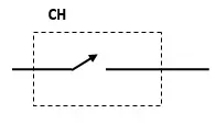
A chopper uses high speed to connect and disconnect from a source load. A fixed DC voltage is applied intermittently to the source load by continuously triggering the power switch ON/OFF. The period of time for which the power switch stays ON or OFF is referred to as the chopper’s ON and OFF state times, respectively.
Choppers are mostly applied in electric cars, conversion of wind and solar energy, and DC motor regulators.
Symbol of a Chopper
Classification of Choppers
Depending on the voltage output, choppers are classified as −
-
Step Up chopper boost-converter
-
Step Down Chopper Buck-converter
-
Step Up/Down Chopper Buck−boost converter
2. An Electric Vehicle's powertrain with 72V battery pack in shown in the diagram below. The duty ratio for acceleration operation is 'd1' and for the braking operation the duty ratio is 'd2'.
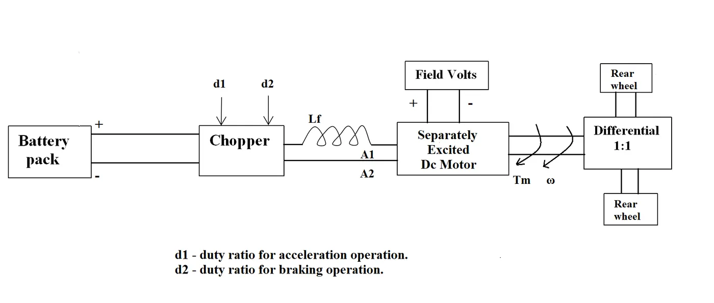
The other parameters of the electric vehicle is given below,
Motor and Controller Parameters:
Rated Armature voltage= 72 V
Rated armature current= 400 A
Ra= 0.5Ω, KΦ= 0.7 Volt second
Chopper Switching frequency= 400 Hz
The vehicle speed-torque characteristics are given by the below equation

What is EV steady state speed if duty cycle is 70%?
Solution:
@70% duty cycle Voltage across motor terminals = Battery voltage * duty cycle = 72 * 0.7 = 50.4 V
We know that in DC motor from torque equation,
T = (V.kΦ/Ra) – (kΦ^2.ω/Ra) = (50.4*0.7/0.5)-(0.7^2* ω/0.5) = 70.56 – 0.98ω
For steady state speed, the motor and vehicle speed torque characteristics should be equal.
Therefore,
70.56 – 0.98ω = 24.7 + (0.0051)ω2
0.0051ω2 + 0.98ω – 45.86 = 0
By solving this equation, ω = 38.91 rad/s
Therefore, the steady state speed of EV @70% duty cycle is 38.91 rad/s
3. Develop a mathematical model of a DC Motor for the below equation using Simulink.
ω= V/Kϕ-Ra/Kϕ^2.T
Mathematical model of a DC Motor for the above equation using Simulink:
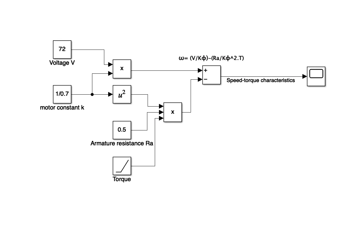
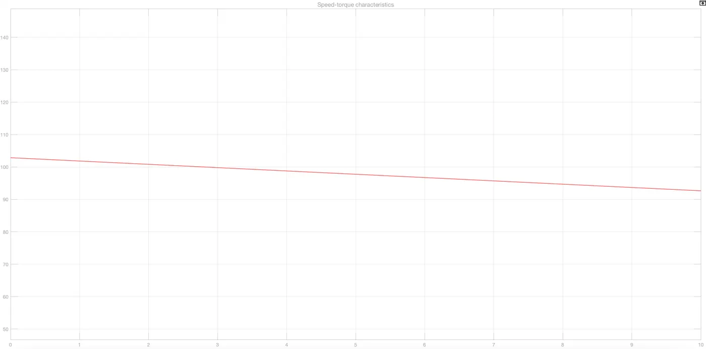
In this model: Constant blocks are used for voltage, motor constant, armature resistance. For torque here ramp block is used as an input. Torque-Speed characteristics is viewed in the scope as shown below.
Speed Vs Torque characteristics
4. Refer to the blog on below topic:
Induction Versus DC brushless motors by Wally Rippel, Tesla
Explain in brief about author’s perspective.
Induction Versus DC Brushless Motors:
Wally rippel has seen the making of EVs for a long time. His perspective was on advancement happening in the EV technology and the telling no particular motor will fulfil all the requirements. With his experience he was sharing the changes happened in the battery technology where lead acid batteries were replaced with Lithium ion batteries, Brushed DC motors were replaced with Brushless DC motor or Induction motor and Contactors used previously were replaced with inverters in the present day world.
His explanation about Brushless DC motors and Induction motors:
With brushless machines, the rotor includes two or more permanent magnets that generate a DC magnetic field. This magnetic field enters the stator core, interacts with currents flowing within the windings to produce a torque interaction between the rotor and stator. As the rotor rotates, it is necessary that the magnitude and polarity of the stator currents be continuously varied such that the torque remains constant and the conversion of electrical to mechanical energy is optimally efficient. The device that provides this current control is called an inverter. Without it, brushless motors are useless motors.
Unlike the DC brushless rotor, the induction rotor has no magnets – just stacked steel laminations with buried peripheral conductors that form a “shorted structure.” Currents flowing in the stator windings produce a rotating magnetic field that enters the rotor. In turn, the frequency of this magnetic field as “seen” by the rotor is equal to the difference between the applied electrical frequency and the rotational “frequency” of the rotor itself. Accordingly, an induced voltage exists across the shorted structure that is proportionate to this speed difference between the rotor and electrical frequency. In response to this voltage, currents are produced within the rotor conductors that are approximately proportionate to the voltage, hence the speed difference. Finally, these currents interact with the original magnetic field to produce forces – a component of which is the desired rotor torque.
He explains about the torque produced by the two motors. DC machines have higher starting torque and high running peak torque capabilities whereas in IM when operated from utility power they have limited starting and running torque. But adding an inverter and feedback loops to power IM, variable speed becomes possible and is capable of competing with BLDC motor.
In BLDC heat generation in rotor is less, rotor cooling is easy and efficiency is higher. BLDC can operate at unity power factor whereas in IM power factor will be at the best 85%. As the size increases BLDC magnetic losses increases but in IM the magnetic losses does not necessarily increases which makes it more suitable where high performance is desired. IM are more difficult to control, more complex and difficult to understand.
BLDC drives are likely to dominate in hybrid and plug-in hybrid vehicles and IM will likely to dominate in pure EV. For both the machines much of the hardware is common which means that both machines live and work side by side in hybrid vehicles and EVs.