Week -2
Aim - Make a Simulink model of Doorbell using solenoid block.
Condition - when the switch is closed the electromagnet receives electrical power from the battery and pulls the metal arm to hit the bell producing sound. Create a situation where the switch is closed for 2 seconds and then released. Observe the physical movement of the plunger.
Mechanism - When the switch is closed, the current supply from the battery passes through the circuit and enters into the solenoid. The solenoid works under the principle of electromagnetism. The current passes through the spring, due to this electromagnetism induced in coils. This force moves the plunger aside. The plunger hits the metal and the metal produces sound with damping.
- Open Simulink from MATLAB and select the blank model.
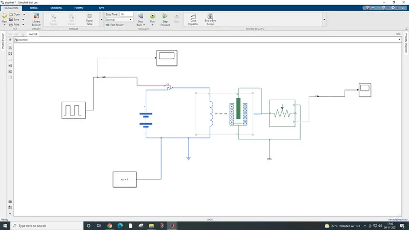
- Firstly, we need to add the switch to the system. Add a switch(of electricals) from the library. The switch should be operated for 2 seconds. This operation can be done by adding a pulse generator block with a phase delay of 2 seconds. Give amplitude 1 and phase width as 50% and frequency 4.
- The Simulink system should be converted into a physical system for operating the switch. Add Simulink-PS convertor add join all connections to switch as shown.
- For knowing the pulse given to the switch, we are adding a scope block.
- Add a battery block for the current supply to the circuit. Join with the switch.
- Add a solenoid block and join the connections to the battery and the switch. The current is supplied through the solenoid spring. Due to this electromagnetism developed in coils moves the plunger into motion. The motion of the plunger should be sensed and we use another block for it.
- An ideal translational motion sensor is added. The point 'R' is joined with 'R' and point 'P' is given out for knowing the position of the plunger.
- A mechanical reference block is added and point 'C' is connected to it.
- For knowing the position in plot form, we add a scope block. Here we convert physical form to Simulink form by connecting each other with the Simulink-PS converter block.
- Electrical reference is given near the battery.
- Solver configuration block is added and joined with the circuit.
- Run the simulation for 10 seconds.
Input scope -
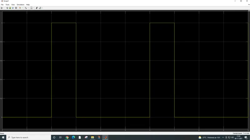
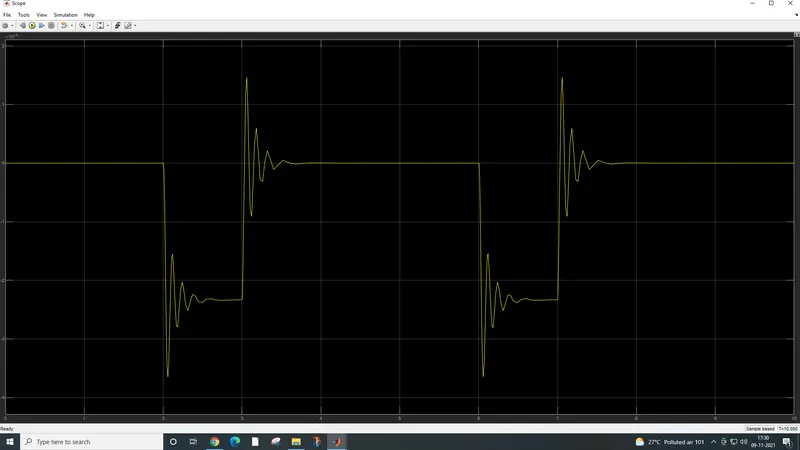
Output Scope -
2. Use a thermistor to sense the temperature of a heater & turn on or turn off the fan
Condition -
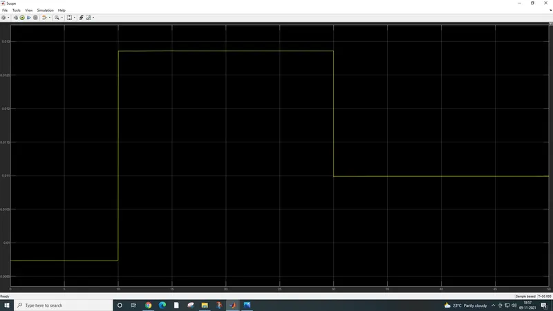
Temperature source: 20 °C from 0 to 10 seconds, 27 °C from 10 to 30 seconds, 23 °C from 30 to 50 seconds
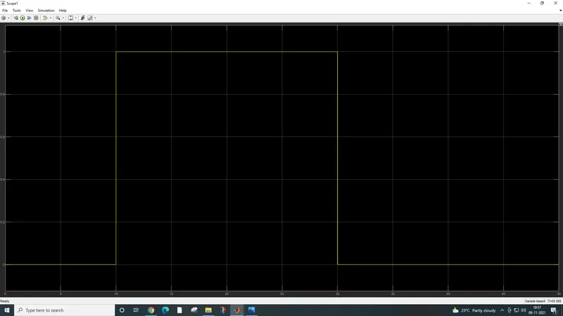
Fan conditions: ON if the temperature is above 25 °C, OFF otherwise.
Thermistor -
A thermistor is a resistance thermometer or a resistor whose resistance is dependent on temperature. The term is a combination of “thermal” and “resistor”. It is made of metallic oxides, pressed into a bead, disk, or cylindrical shape, and then encapsulated with an impermeable material such as epoxy or glass.
Signal builder-
The Signal Builder block allows you to create interchangeable groups of piecewise linear signal sources and use them in a model. You can quickly switch the signal groups into and out of a model to facilitate testing. In the Signal Builder window, create signals and define the output waveforms. To open the window, double-click the block.
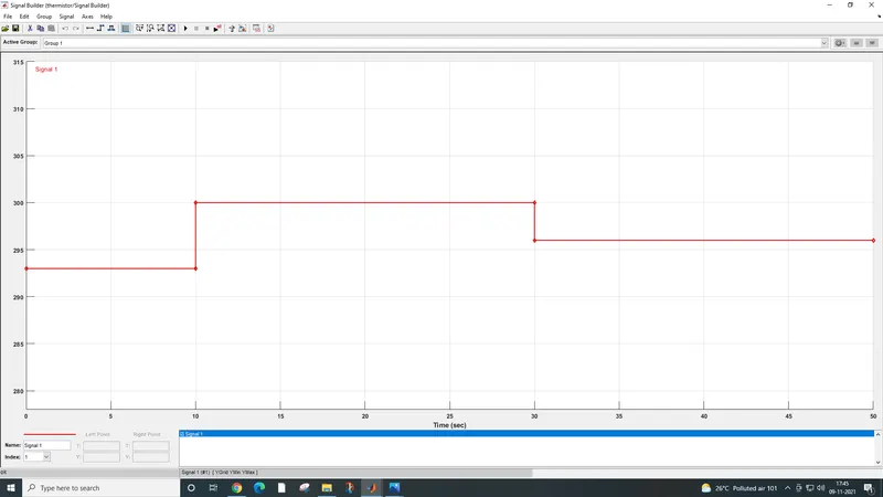
Given Inputs -
| SR NO | POINT | TEMPERATURE | TIME |
| 1 | Point 1 | 293 k | 0 sec |
| 2 | Point 2 | 293 k | 10 sec |
| 3 | Point 3 | 300 k | 10 sec |
| 4 | Point 4 | 300 k | 30 sec |
| 5 | Point 5 | 296 k | 30 sec |
| 6 | Point 6 | 296 k | 50 sec |
Simulink -PS converter -
The Simulink-PS Converter block converts the input Simulink signal into a physical signal. Use this block to connect Simulink sources or other Simulink blocks to the inputs of a Simscape physical network.
Ps- Simulink converter -
The PS-Simulink Converter block converts a physical signal into a Simulink output signal. Use this block to connect outputs of a Physical Network diagram to Simulink scopes or other Simulink blocks.
Controlled Temperature source -
The Controlled Temperature Source block represents an ideal source of thermal energy that is powerful enough to maintain specified temperature differences across the source regardless of the heat flow consumed by the system. Connections A and B are thermal conserving ports corresponding to the source inlet and outlet, respectively. Port S is a physical signal port, through which the control signal that drives the source is applied. You can use the entire variety of Simulink signal sources to generate the desired heat flow variation profile. The temperature differential across the source is directly proportional to the signal at the control port S.
Thermal Reference -
The Thermal Reference block represents a thermal reference point, that is, a point with an absolute zero temperature, with respect to which all the temperatures in the system are determined.
Solver Configuration -
Each physical network represented by a connected Simscape™ block diagram requires solver settings information for simulation. The Solver Configuration block specifies the solver parameters that your model needs before you can begin the simulation.
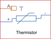
Thermistor -
A Thermistor is a type of resistor whose resistance depends on temperature, more so than in standard resistors. The word is a combination of Thermal + Resistor.
Battery -
In Battery positive terminal is connected with the switch and the negative terminal is connected to “Electric Reference”.
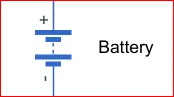
The Battery block implements a generic dynamic model that represents the most popular types of rechargeable batteries.
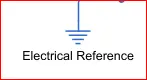
Electric reference -
The Electrical Reference block represents an electrical ground. Electrical conserving ports of all the blocks that are directly connected to the ground must be connected to an Electrical Reference block. A model with electrical elements must contain at least one Electrical Reference block.
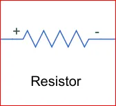
Resistor -
The Resistor block model a linear resistor, describe with the following equation.
Voltage Sensor -
The Voltage Sensor block represents an ideal voltage sensor, that is, a device that converts voltage measured between two points of an electrical circuit into a physical signal proportional to the voltage.
Constant -

The Constant block generates a real or complex constant value signal. Use this block to provide a constant signal input. The block generates scalar, vector, or matrix output, depending on:
-
The dimensionality of the Constant value parameter
-
The setting of the Interpret vector parameters as 1-D parameter
The output of the block has the same dimensions and elements as the Constant value parameter. If you specify for this parameter a vector that you want the block to interpret as a vector, select the Interpret vector parameters as a 1-D check box. Otherwise, if you specify a vector for the Constant value parameter, the block treats that vector as a matrix.
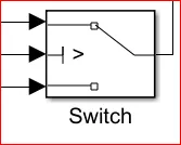
Switch -
The Switch block passes through the first input or the third input signal based on the value of the second input. The first and third inputs are data input. The second input is a control input. Specify the condition under which the block passes the first input by using the Criteria for passing the first input and Threshold parameters.
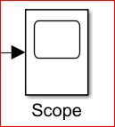
Scope -
The scope is connected with the Ideal Translation Motion Sensor to get the output. The real-time Scope block acquires data in chunks of size Number of samples from the real-time application that is executing on the target computer.
Display -
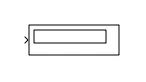
The Display block shows the value of the input data. You can specify the frequency of the display. For numeric input data, you can also specify the format of the display. If the block input is an array, you can resize the block vertically or horizontally to show more than just the first element. If the block input is a vector, the block sequentially adds display fields from left to right and top to bottom. The block displays as many values as possible. A black triangle indicates that the block is not displaying all input array elements.
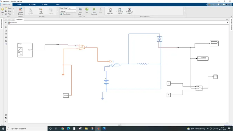
The output of the model-